


Simple steps to CAD
Generate your CAD model with our reverse engineering solution

From 3D scan to CAD model with reverse engineering
Looking for a software solution that makes reverse engineering easy?
Our reverse engineering solution is ready to take your data to the next level. Scan your parts in ZEISS INSPECT or any other software and import your STL, PLY and ASCII-Formats to the reverse engineering software. It just takes a few guided steps to obtain a high-precision CAD model that can be exported to standard CAD formats like IGES, STEP or SAT. So, whatever your reverse engineering task: get there easily and fast.
A powerful software for reverse engineering

Guided workflow
Our reverse engineering solution makes it easy to generate a CAD model from scan data such as polygon meshes or point clouds and guides you step by step through the workflow.

High accuracy
The reverse engineering software delivers CAD surfaces with the highest accuracy. This is essential if you want to produce plastic parts that have high accuracy requirements.

Effective functions
Prepare your data with features such as hole filling and flattening, and proceed with features such as dynamic best fit or extrusion.
Get your CAD model – whatever the shape
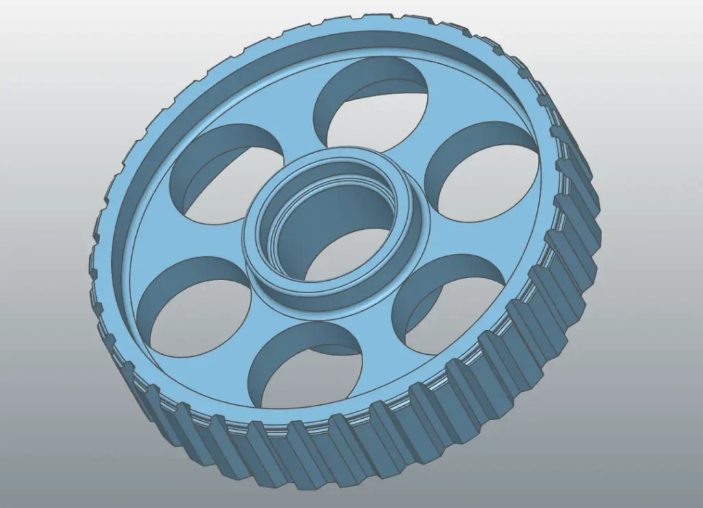
Geometric parts
Reverse Engineering for geometric forms? Export your mesh to the reverse engineering software and start to create, combine, extract and adjust. You are in control of the whole process and generate exactly the result you need.
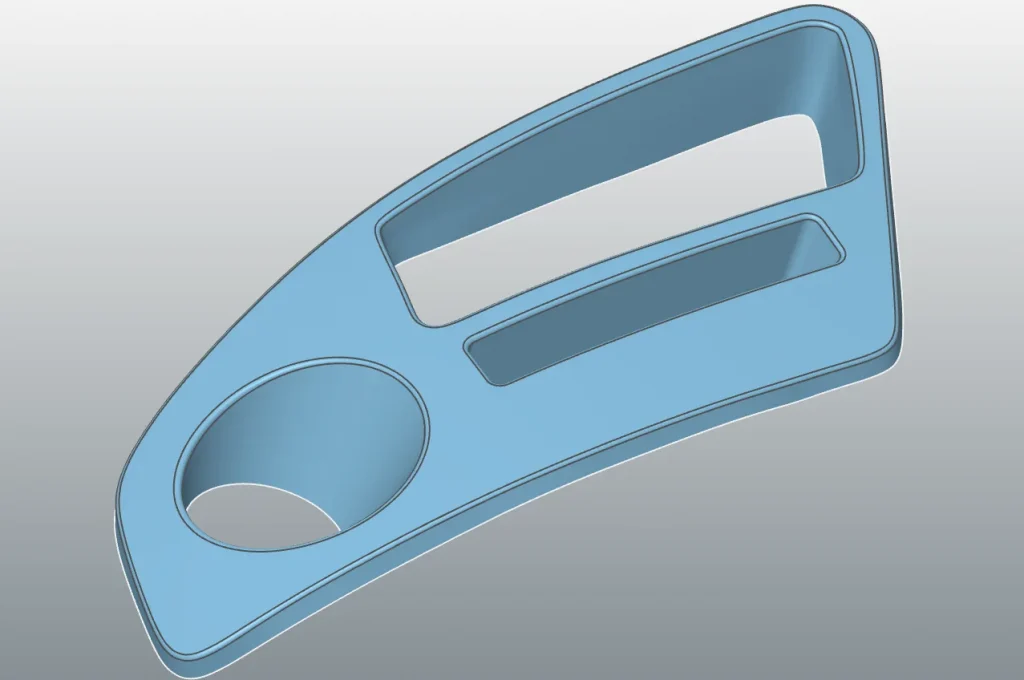
Freeform surfaces
The software offers you various functionalities to achieve the highest accuracy for freeform surfaces. To convert your mesh, use “Surface Approximation to Points” for example. Afterwards, the software guides you through every step of the way to your mold.
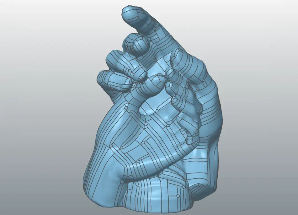
Organic shapes
Whether you want to create a CAD model for a part with an organic shape or continue reverse engineering, designing and modeling with a CAD – you will get there with just a few clicks. Have a look at the video.
Your easy way to a high-precision CAD model
Pro
Import CAD files
Advanced mesh editing
Automatic segmentation
Alignment of scan data to CAD
Global / Fine scan data alignment
Mesh outline / Stacked cross sections
Loft / Sweep / Extrude / Revolve
Trim / Boolean / Patterns
Helix / Roll / Unroll
Shell / Offset / Thicken
Constant and Variable filleting and chamfer
Fit Surface
Advance automatic freeform
Hybrid modelling
CAD correction - Move / Draft / Extend surface
Real-time deviation analyser
Export to IGES / STEP / Parasolid
For Solidworks
Work inside SOLIDWORKS Desktop 3D CAD
Import large scans to SOLIDWORKS
Meshes as native SOLIDWORKS features
Polygon reduction and smoothing
Unroll scan
Extract reference geometry (incl. symmetry plane)
Align to space, to CAD
Multi-scan alignment
Cross-sections: parallel, rotational, outline
Fit lines/arcs & complex profiles for 2D sketching
3D sketching on scan data
Best-fit surfaces
Freeform surface modelling
Real-time deviation analyser
3D colour map: CAD vs. Scan
One-click freeform
Do you have further questions on reverse engineering?
Don’t hesitate to contact us. We’re more than happy to help.