Archäologie trifft 3D Scan-Technologie
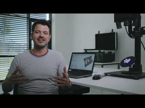
Museum of Research Schöningen: Archeology meets 3D Scan-Technology
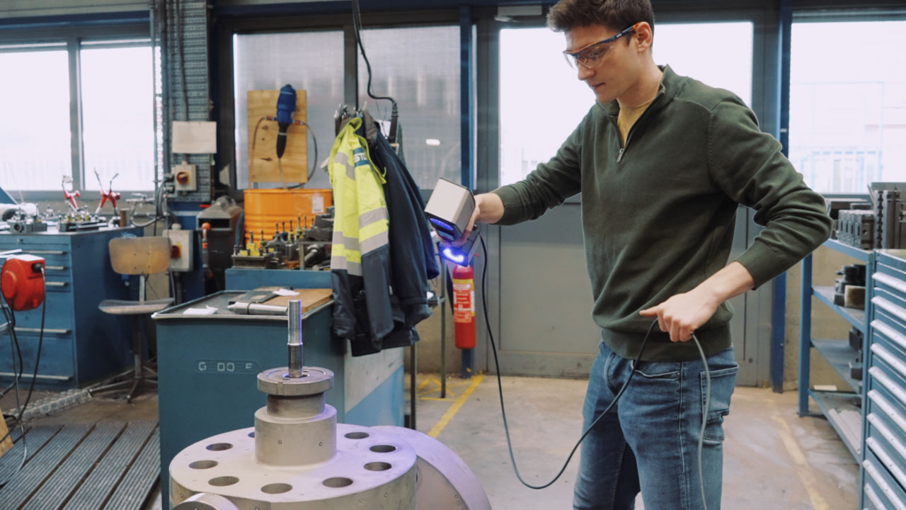
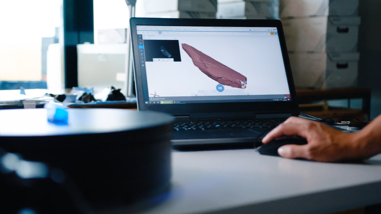
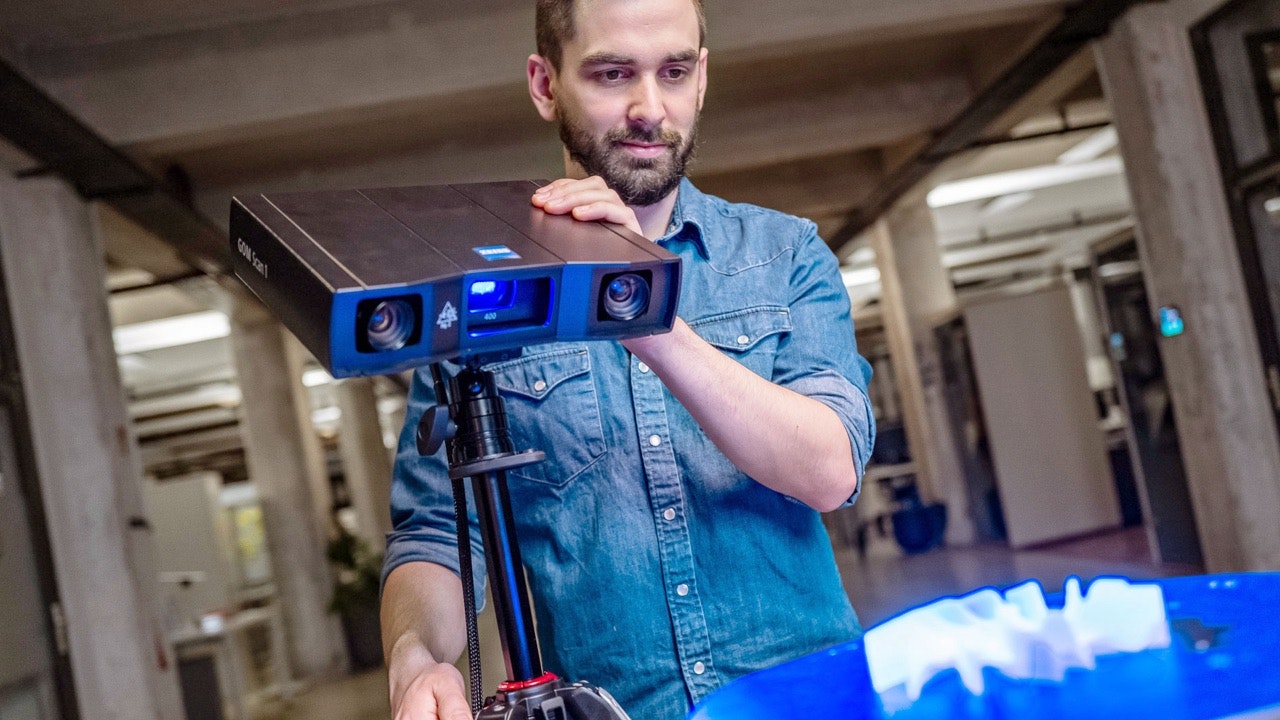
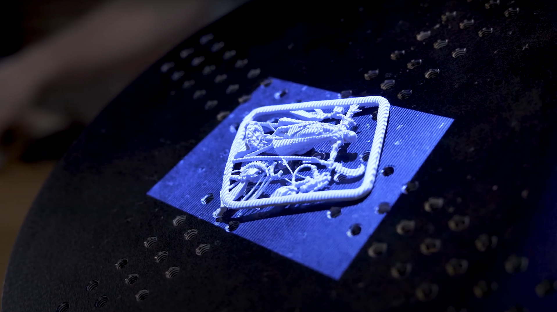
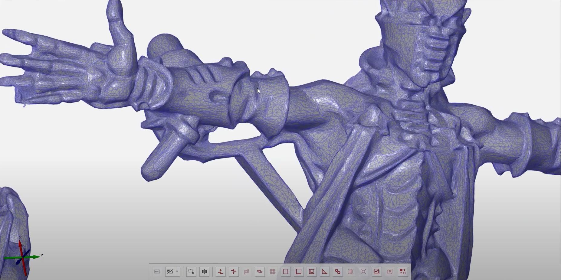
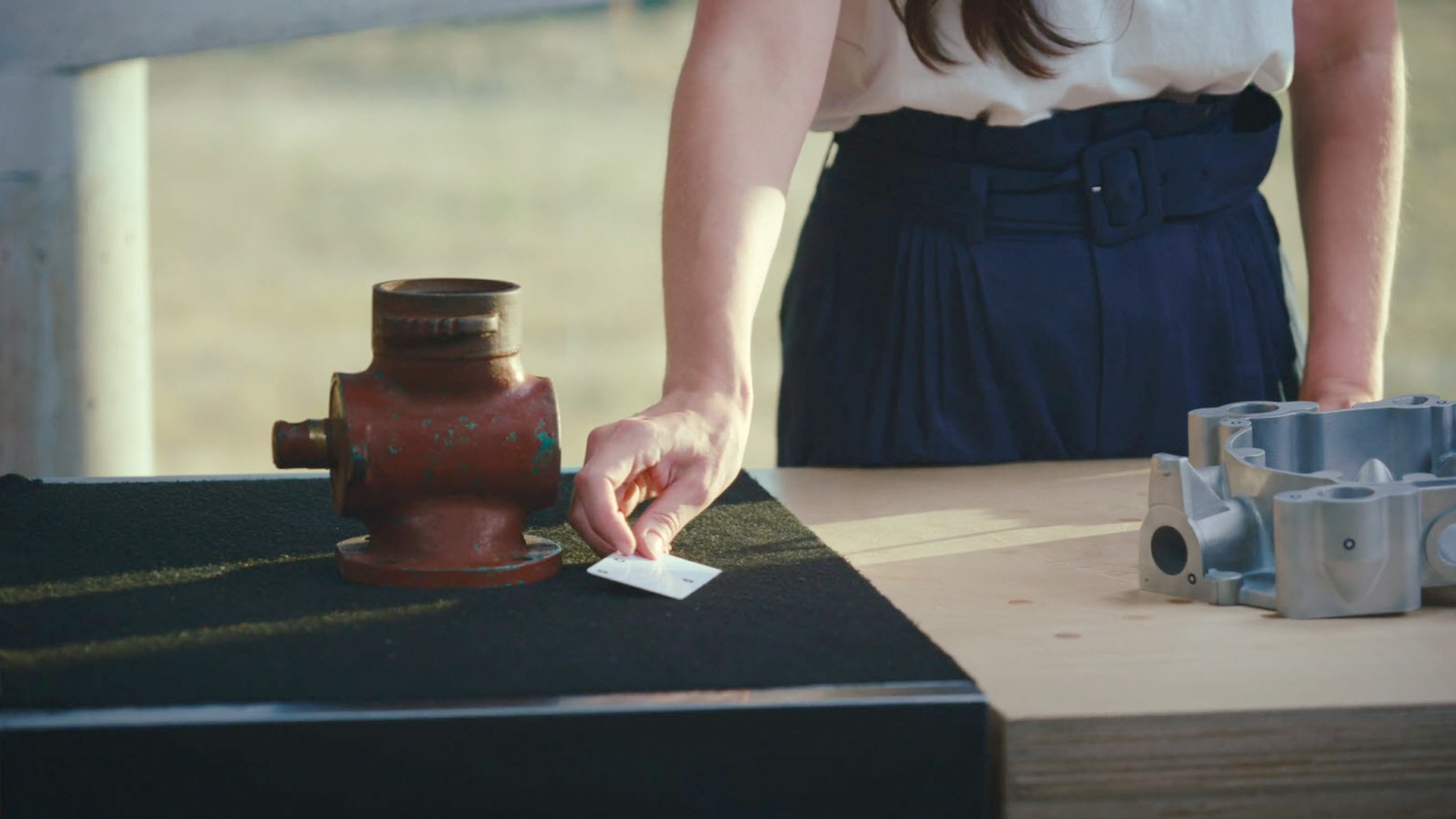
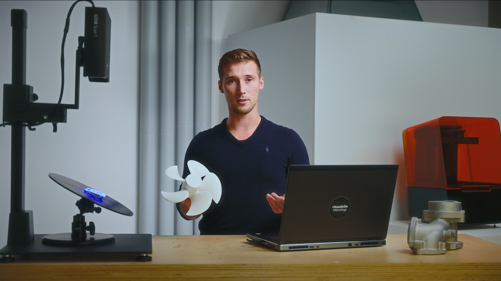
300.000 years of history are archived at the Museum of Research in Schöningen. 3D metrology solutions help to collect detailed information about the findings. Whether the reconstruction of parts or precise surface inspection: Thus the GOM Scan 1 and the software solution allow an insight into the past, which is accessible to everyone. Learn more about the Museum: https://forschungsmuseum-schoeningen.de/home
Neueste Videos
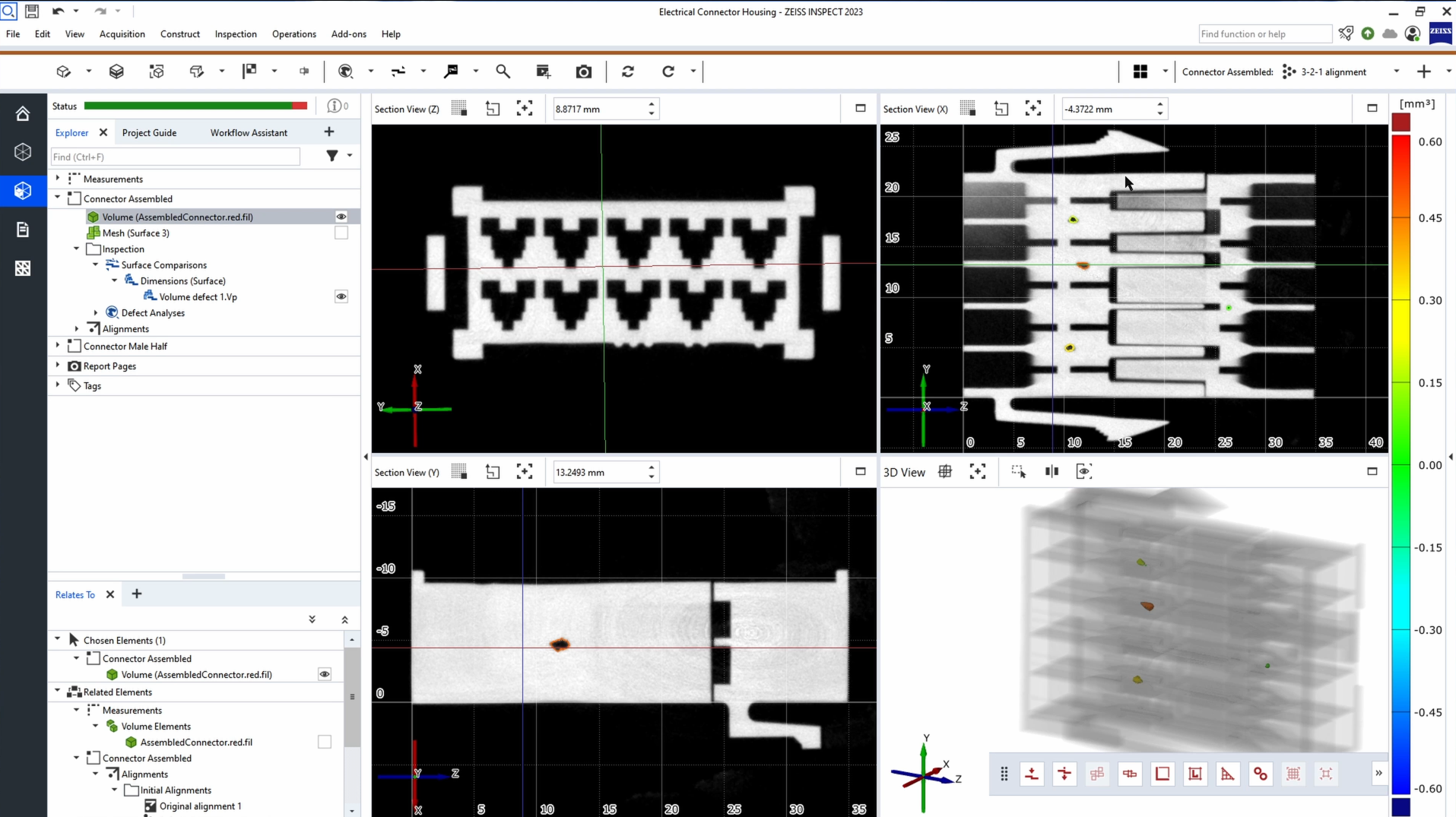
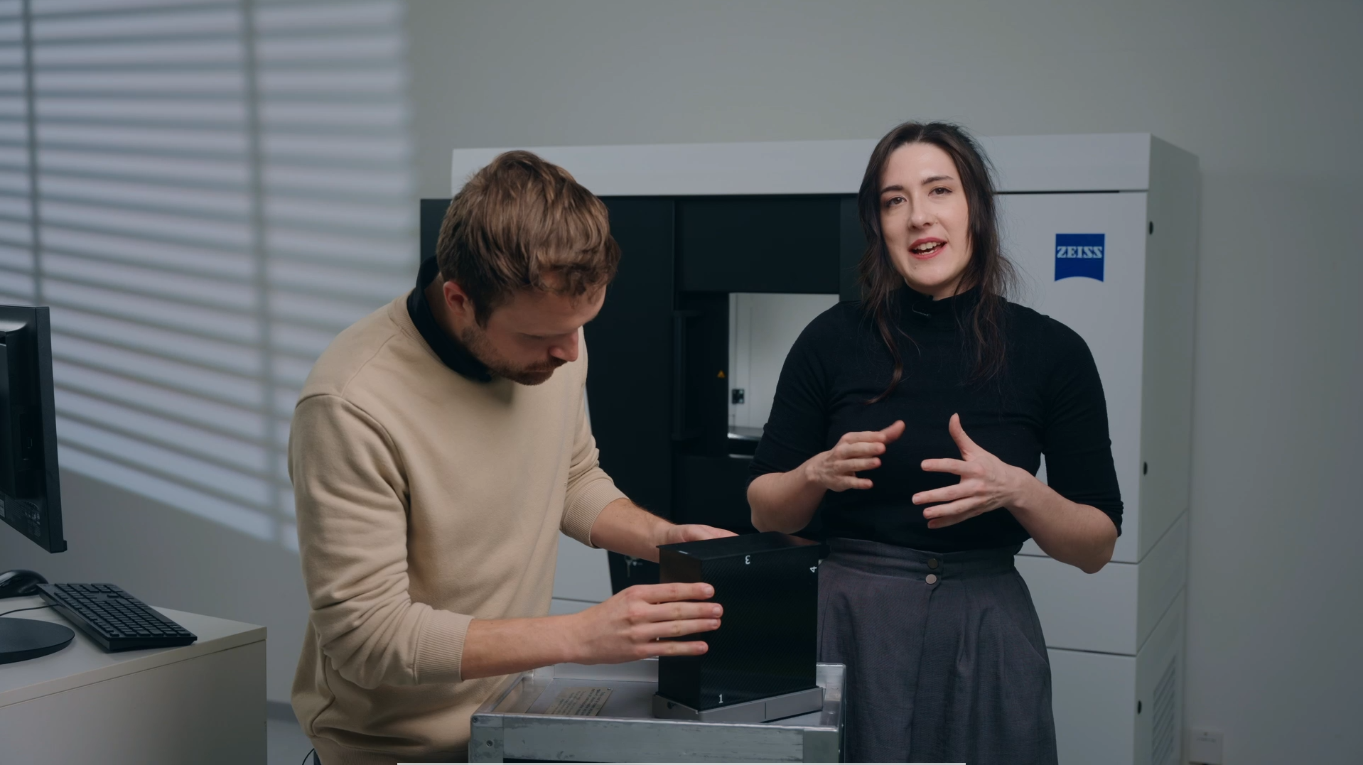
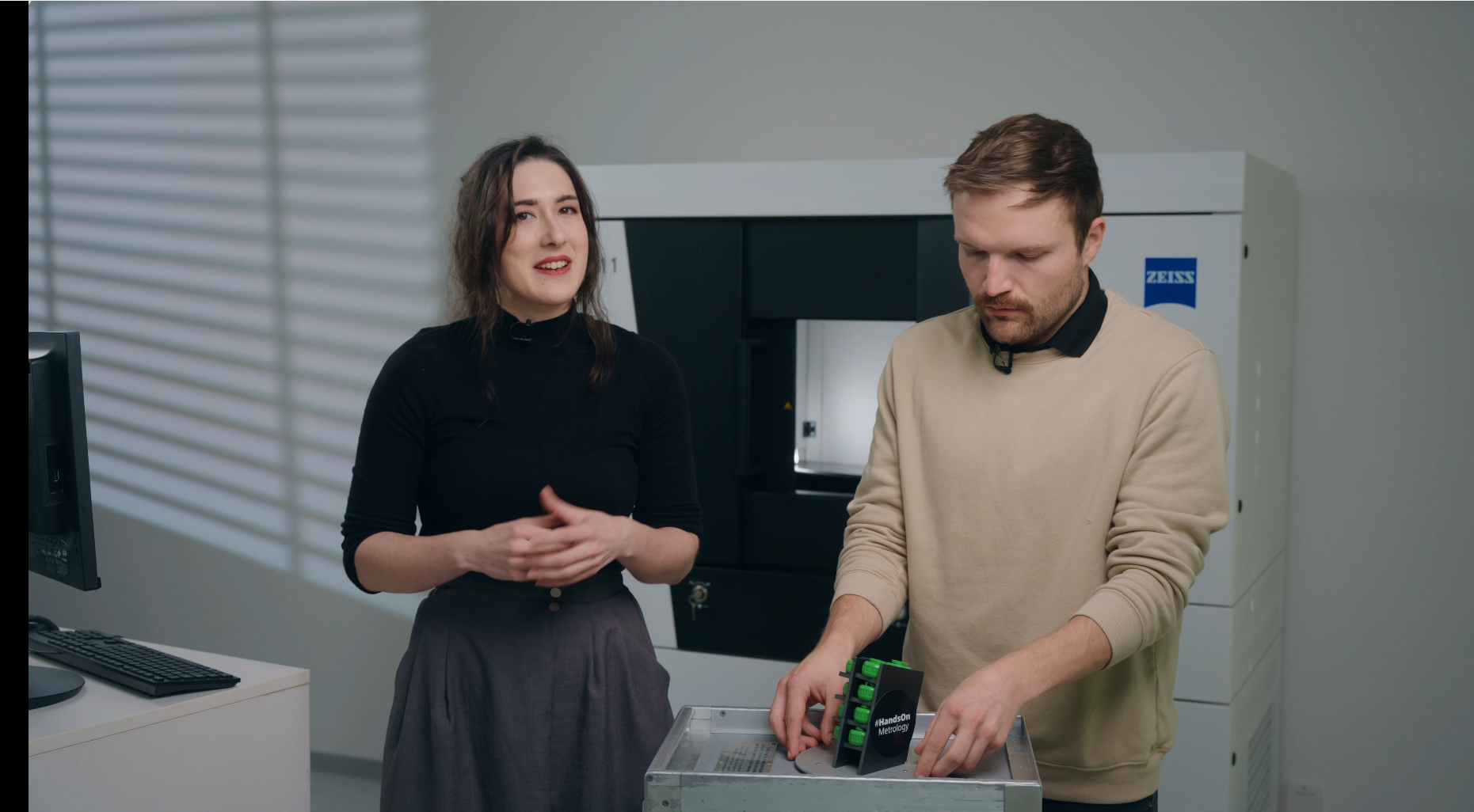
METROTOM 1: How to inspect the inside of electronic connector housings
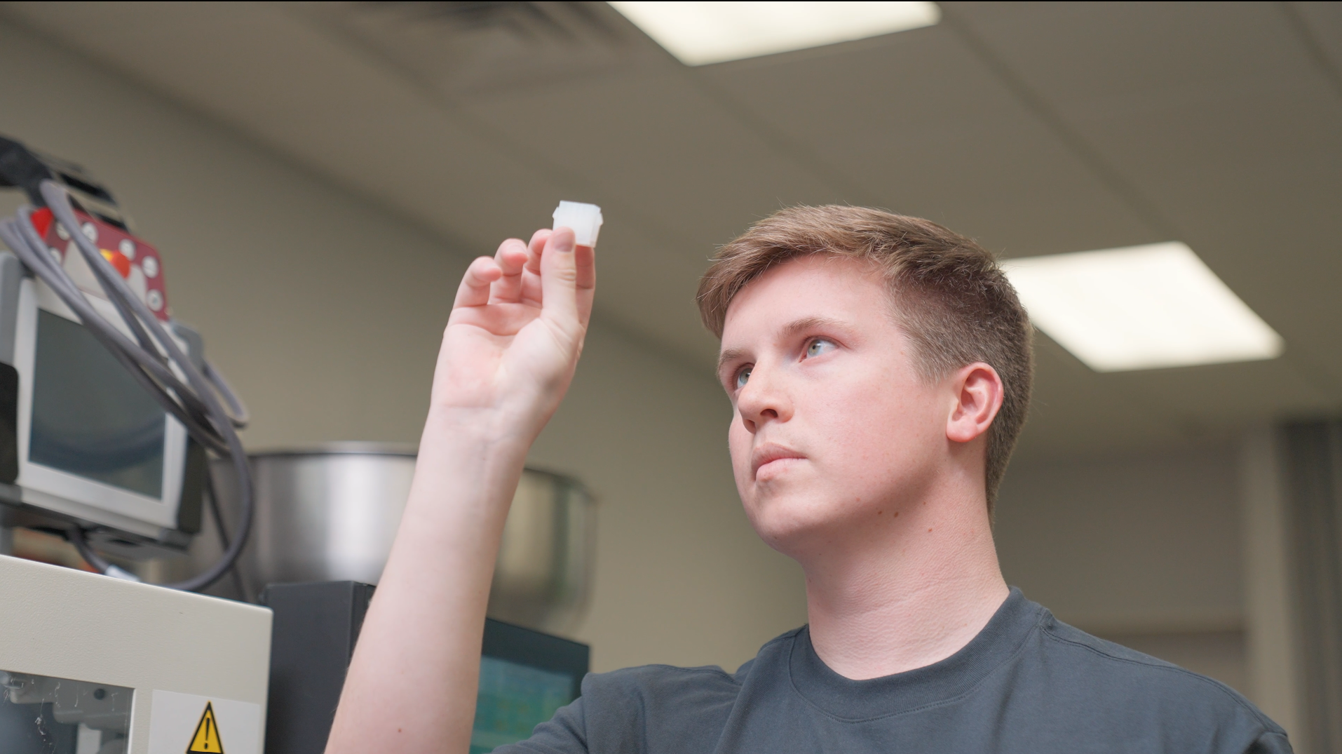
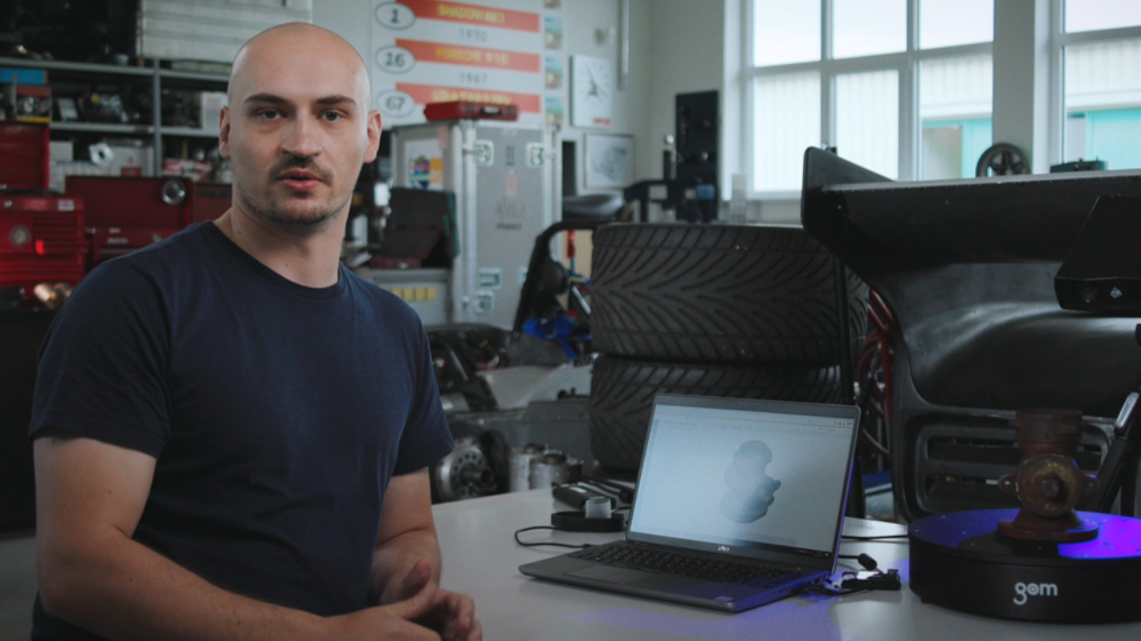
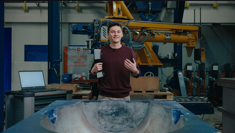
Did you know that the 3D scanner METROTOM 1 is ideal for the overall inspection of electronic connectors housings? Let Alex show you how a simple 3D scan – powered by CT technology – can provide you with valuable data to determine the external and internal part quality.
Do you have any question on our 3D scanners? Contact us via support@HandsOnMetrology.com
Sabelt: High performance seat belts for a safer future
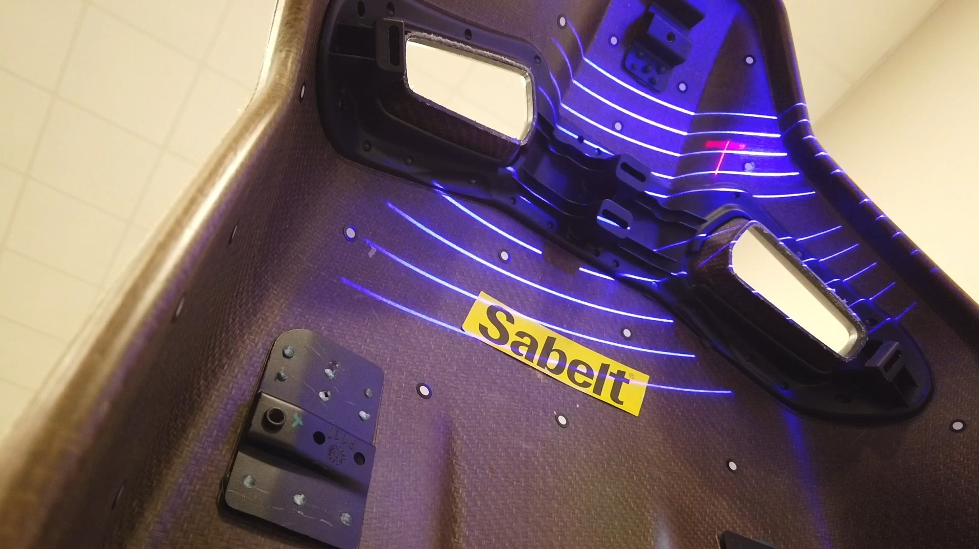
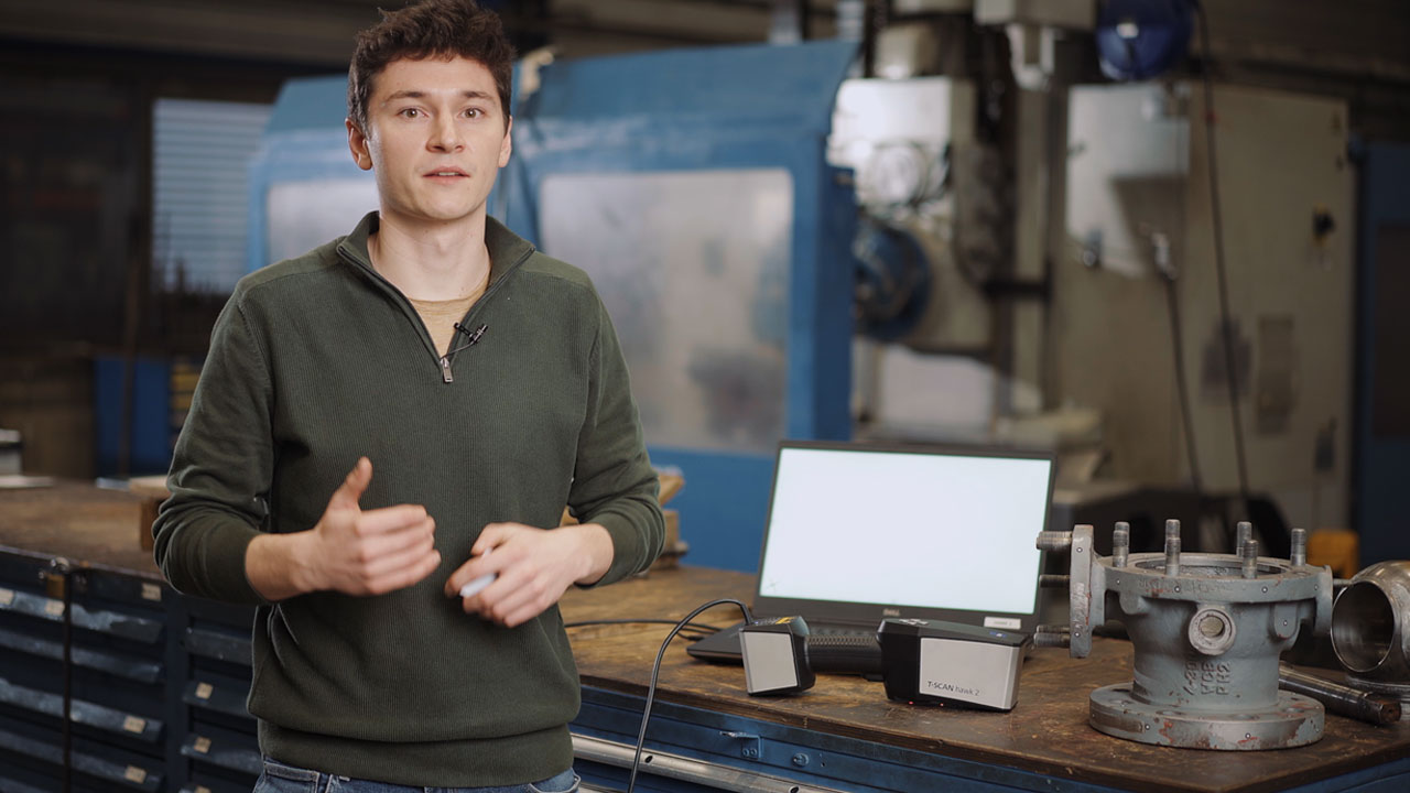
Take a look behind the scenes at Sabelt, the Turin-based international market leader in high performance seat belts and manufacturer of outstandingly good car seats, race suits and other motorsport accessories. Their main goal? To harmonize the three key elements of their business: economic growth, social inclusion and environmental protection. The video shows you what our 3D scanner ZEISS T-SCAN hawk 2 has to do with it. Thanks to our Italian partner Metrologia SpA for sharing this story.
Want to learn more about Sabelt. Visit https://www.sabelt.com/
How to scan large parts using ZEISS T-SCAN hawk 2
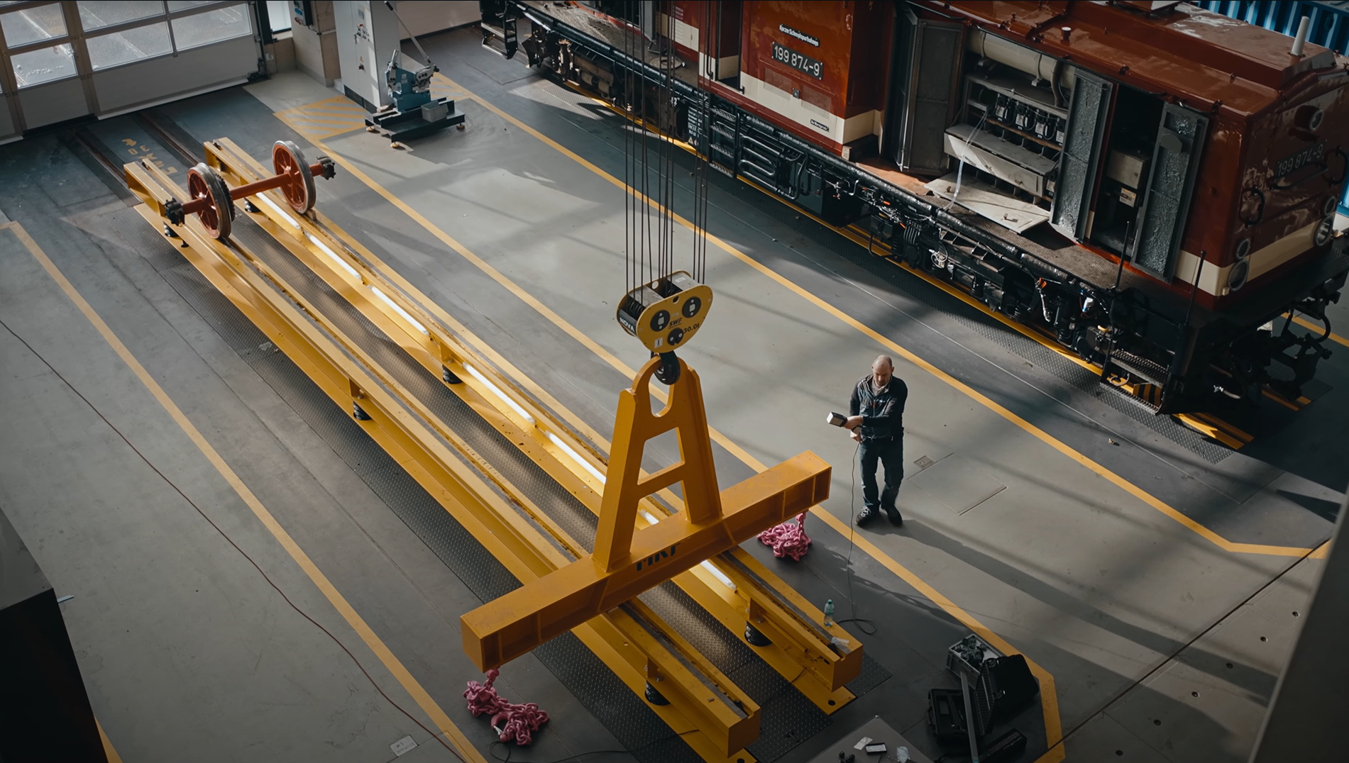
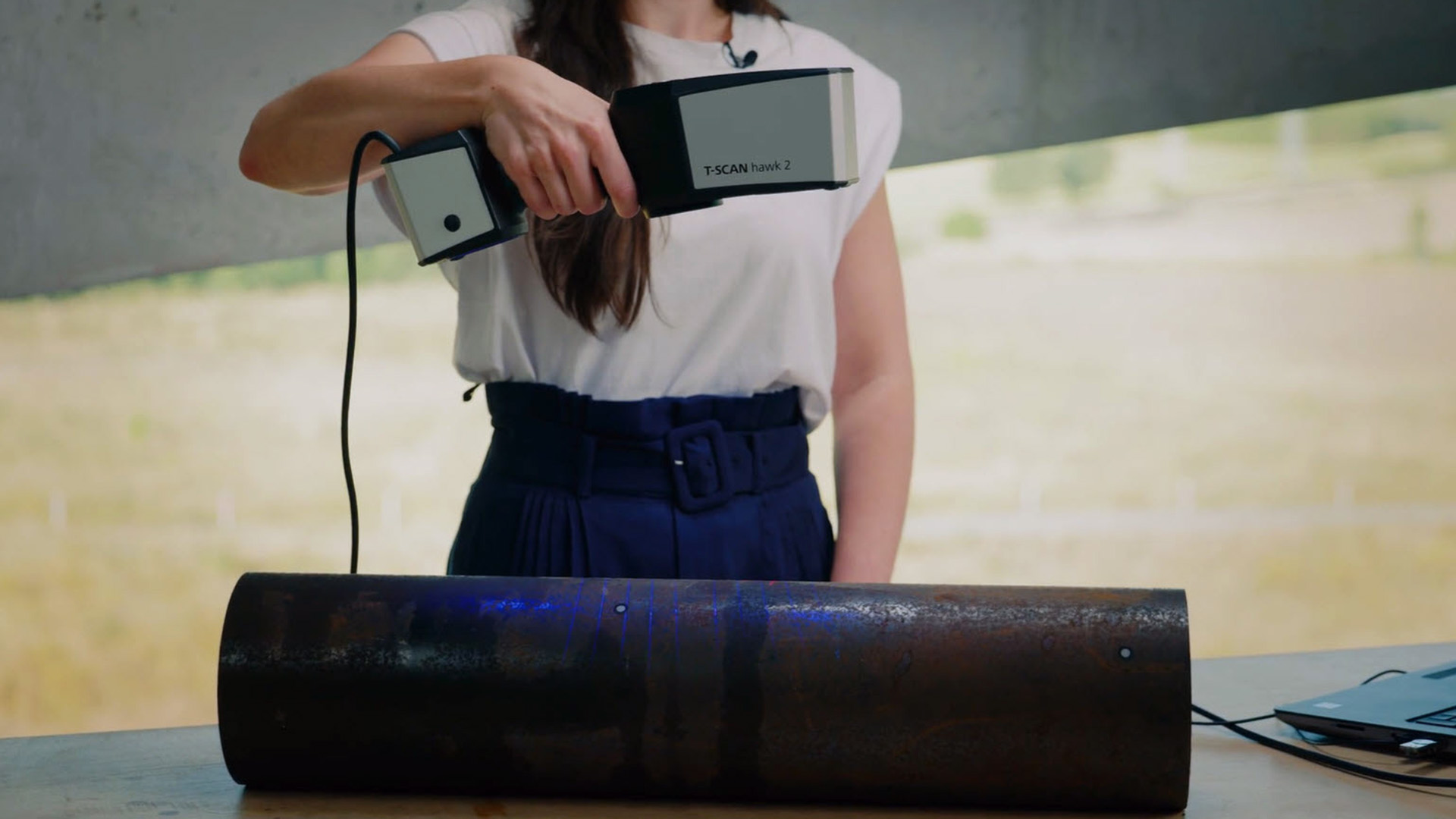
Looking for an easy and intuitive way to 3d scan large parts up to multiple meter? Then the 3D laser scanner ZEISS T-SCAN hawk 2 with the new satellite mode is the right solution for you. Let Matthias show you how it’s done.
Do you have any questions about ZEISS T-SCAN hawk 2? Contact us via support@HandsOnMetrology.com
Beliebteste Videos
How to use ZEISS INSPECT as a presentation viewer
Get an insight from Jonas and learn why he prefers to use ZEISS INSPECT as a viewer whenever he has to present the results of an inspection job to a client or the team.
All functions shown are available in the current software version.
Have you got any questions about ZEISS INSPECT ? Then contact us via email: support@HandsOnMetrology.com
How to 3D scanning for wear control in MRO
Wear and tear of production equipment causes malfunctioning, delays, downtime. In this How to, Roel shows you how 3D scanning is used to implement predictive maintenance – and therefore keep production running efficiently.
Got any questions on 3D scanning? Contact us via support@HandsOnMetrology.com
T-SCAN hawk 2: The new Satellite mode
In this Getting Started we demonstrate how to accurately scan large parts with photogrammetry. The new integrated satellite mode ensures precise pre-referencing. No other features, like coded markers, are necessary. Watch the video to see the T-SCAN hawk 2 unleash its full potential.
Do you want to find out more about the portable 3D laser scanner T-SCAN hawk 2? Visit HandsOnMetrology.com/sessions
T-SCAN hawk 2: The setup
Want to know what to consider when setting up your new T-SCAN hawk 2? Let Aysel show you an easy step-by-step guide for starting your laptop as well as the system. Get ready for your first scan with the T-SCAN hawk 2! Have you got any questions about 3D scanning? Contact us via support@HandsOnMetrology.com
How to use a 3D scanner in confined spaces
In this How to Roel is scanning complex and hard to reach areas of a van interior. Whether for inspection or design purposes – the ZEISS T-SCAN hawk 2 is the perfect fit for extracting accurate and complete dimensions in confined spaces. Got any questions on 3D scanning? Contact us via support@HandsOnMetrology.com
Museum of Research Schöningen: Archeology meets 3D Scan-Technology
300.000 years of history are archived at the Museum of Research in Schöningen. 3D metrology solutions help to collect detailed information about the findings. Whether the reconstruction of parts or precise surface inspection: Thus the GOM Scan 1 and the software solution allow an insight into the past, which is accessible to everyone. Learn more about the Museum: https://forschungsmuseum-schoeningen.de/home
Cutting objects into pieces with Delete by Plane
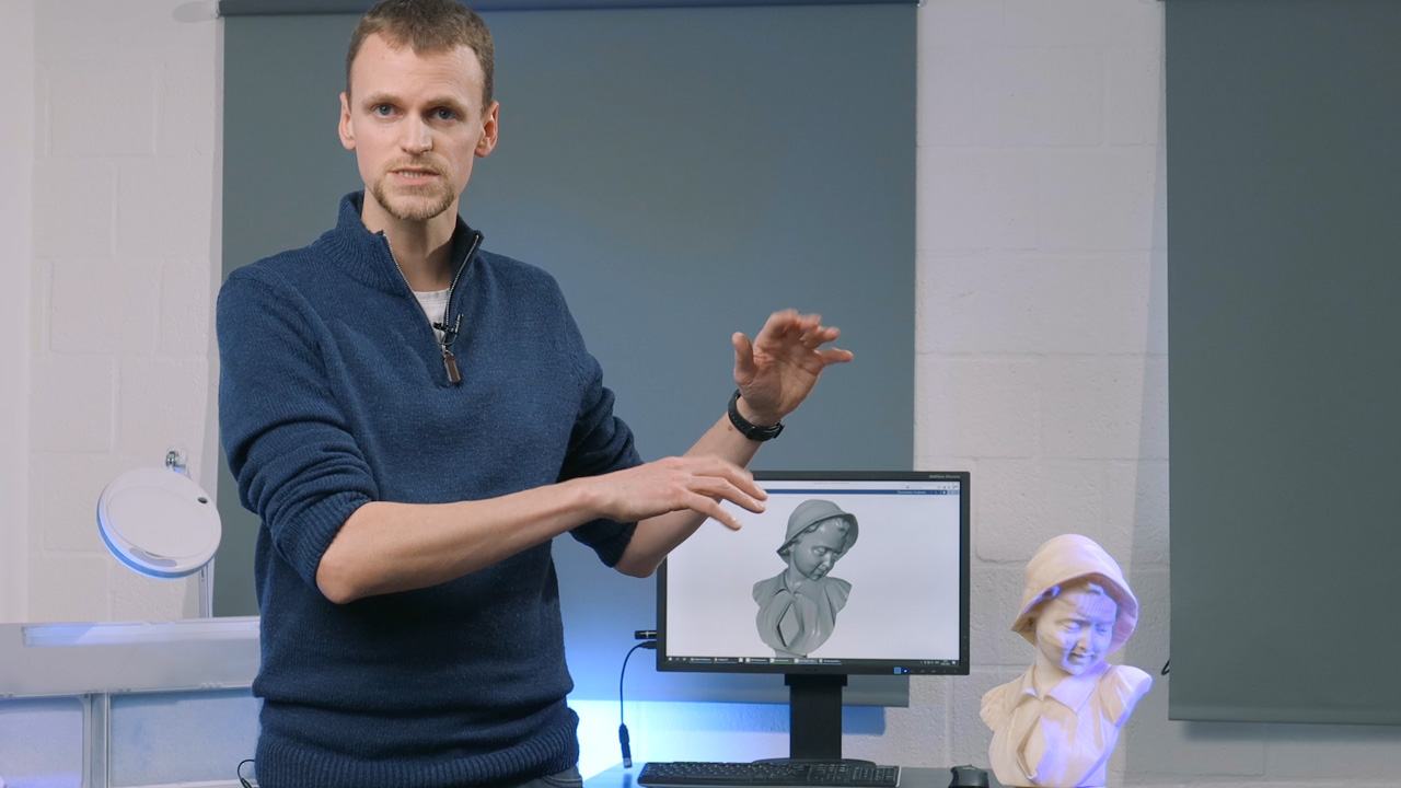
Do you want to print a piece of art that is bigger than the volume of your 3D printer? Jurgen from Tetra Vision shows you an easy way to do just that, using the Delety by Plane function in ZEISS INSPECT.
All functions shown are available in the current software version
Have you got any questions about ZEISS INSPECT? Then contact us via email: support@HandsOnMetrology.com
ZEISS REVERSE ENGINEERING: Tips and tricks
In this video, Josh lets you in on some handy tips and tricks to help you get started even faster with ZEISS REVERSE ENGINEERING. Learn how to bookmark your favorite functions. Discover how the transparency tool can help you get a better look at specific elements. Learn about how the snapshot tool makes it easy for you to create images for reports. Start using the „fit to screen“ icon to get a better view of your part. And minimize clicks by looking at the shortcut list in the user guide.
All functions shown are available in the current software version.
Got any questions on the ZEISS software? Contact us via support@HandsOnMetrology.com
Wie du deine eigenen Ersatzteile scannst & druckst
Wie man Objekte ohne Referenzpunkte scannt
SST Flugtechnik: Flugzeugdesign made in Germany
Maker Portraits
Sabelt: High performance seat belts for a safer future
Take a look behind the scenes at Sabelt, the Turin-based international market leader in high performance seat belts and manufacturer of outstandingly good car seats, race suits and other motorsport accessories. Their main goal? To harmonize the three key elements of their business: economic growth, social inclusion and environmental protection. The video shows you what our 3D scanner ZEISS T-SCAN hawk 2 has to do with it. Thanks to our Italian partner Metrologia SpA for sharing this story.
Want to learn more about Sabelt. Visit https://www.sabelt.com/
HSB: Maintenance of historic steam locomotives
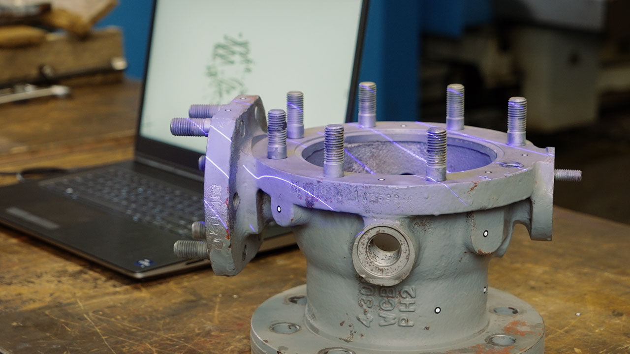
HSB is the largest service provider for public transportation in eastern Germany. They use the state-of-the-art 3D scanning technology of the ZEISS T-SCAN hawk 2 to ensure that their steam locomotives run non-stop and that their traditional drives are preserved for the future. Accurate 3D models of the machines support the maintenance, repair and overhaul – keeping a part of German history alive in the Harz mountains.
Want to learn more about HSB? Visit https://www.hsb-wr.de/startseite/
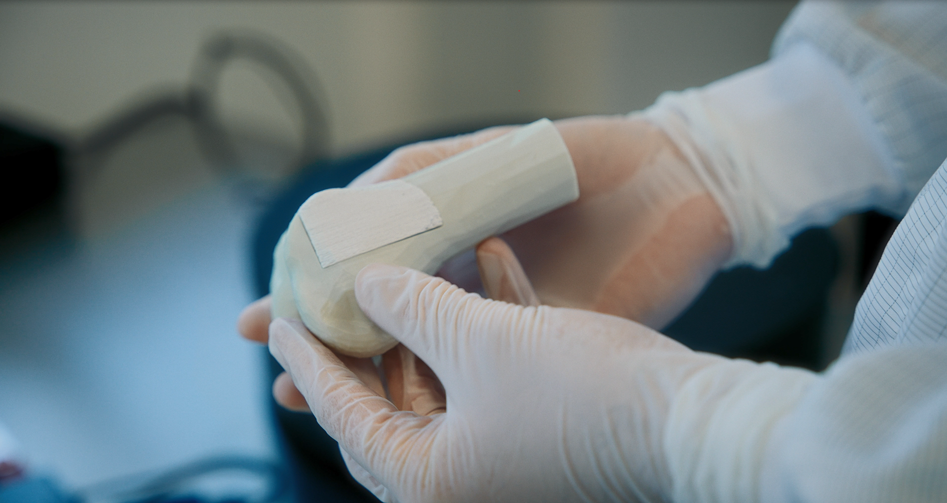
Ossiform: Quality control of 3D printed bone implants
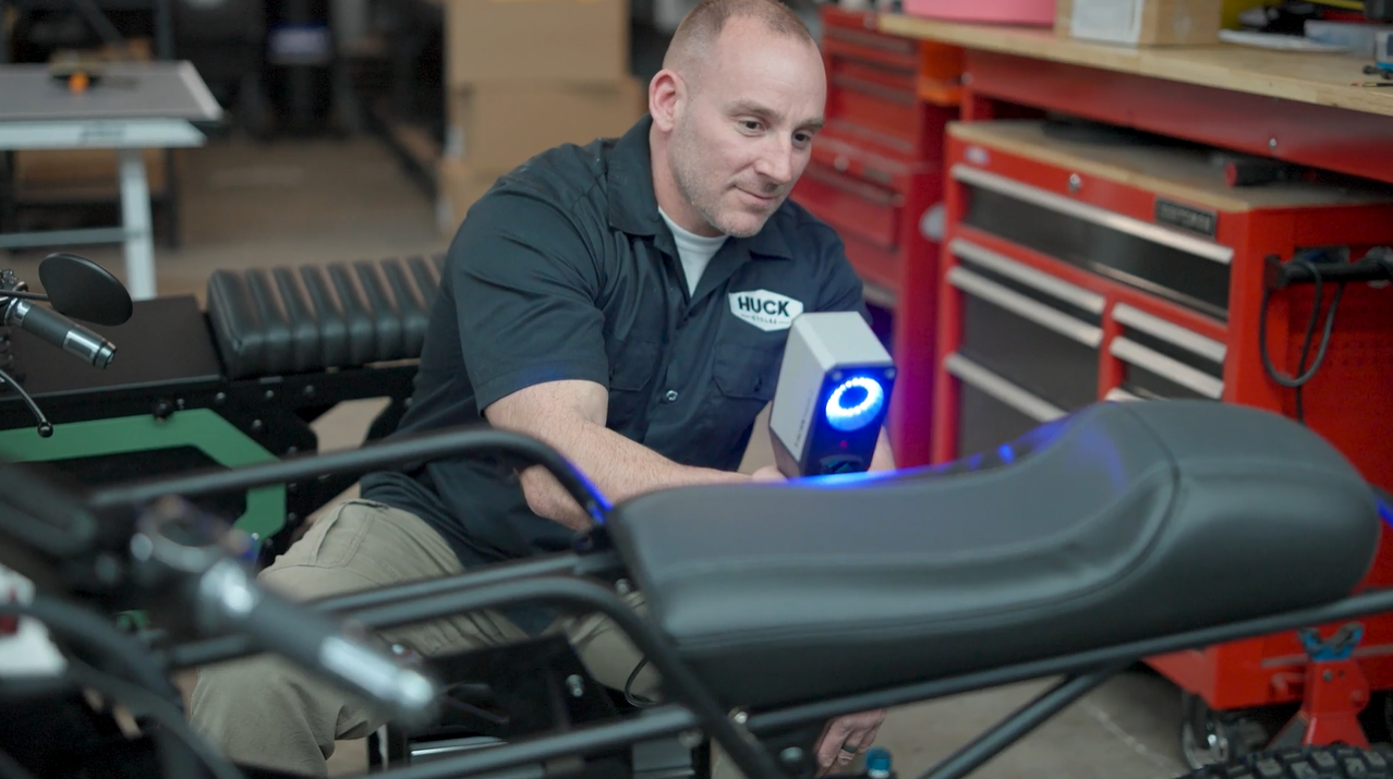
Huck Cycles: Quality control of electric motorcycles
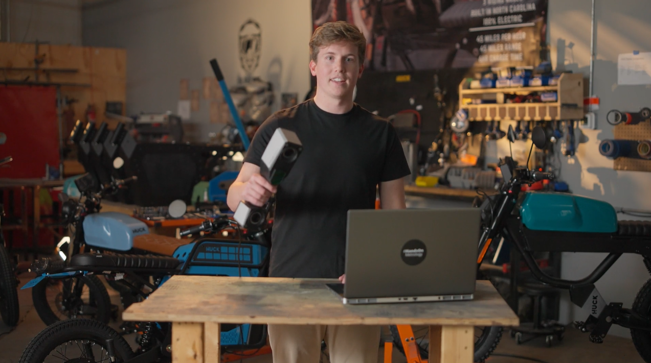
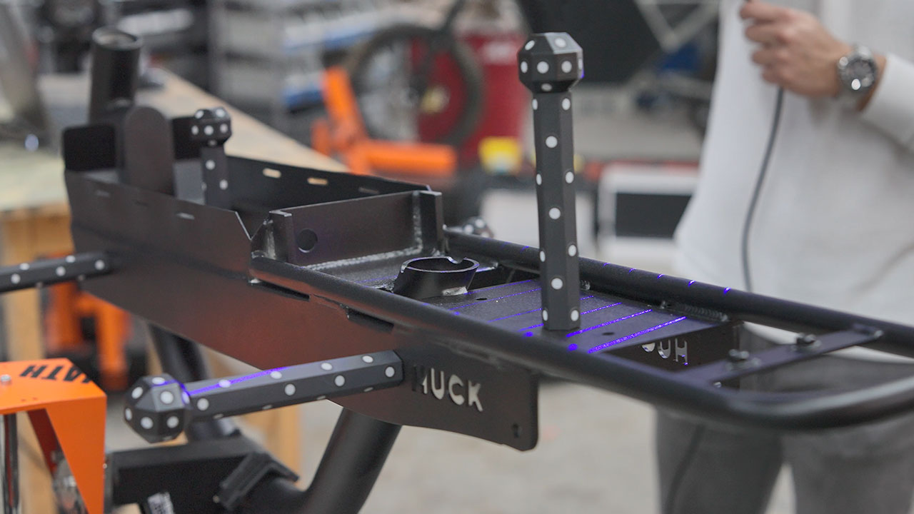
At Huck Cycles it’s all about developing and designing electric motorcycles. The hand-held ZEISS T-SCAN hawk 2 comes into use when exact and fast quality control is needed. With the scanner, controlling each and every single component via a quick scan and CAD comparison is possible – saving the company time and energy, while maintaining high quality motorized vehicles.
Want to learn more about Huck Cycles? Visit www.huckcycles.com
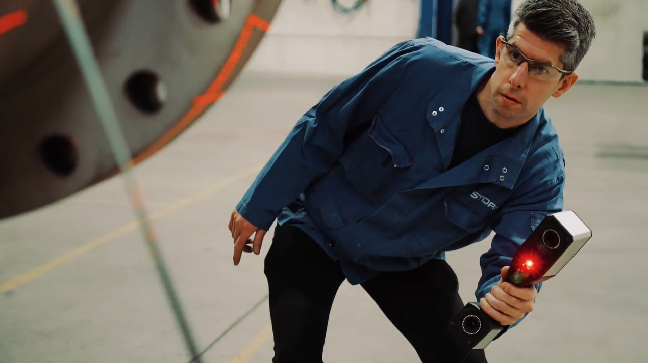
Stork: MRO with portable 3D scanner
MRO processes with the portable ZEISS T-SCAN hawk 2 are the way to go for the company Stork.The flexibility of the scanner is ideal for the indiviudal quality control and reverse engineering tasks of their customers. Have a look at the daily work at Stork company in our new Maker Story.
Museum of Research Schöningen: Archeology meets 3D Scan-Technology
300.000 years of history are archived at the Museum of Research in Schöningen. 3D metrology solutions help to collect detailed information about the findings. Whether the reconstruction of parts or precise surface inspection: Thus the GOM Scan 1 and the software solution allow an insight into the past, which is accessible to everyone. Learn more about the Museum: https://forschungsmuseum-schoeningen.de/home
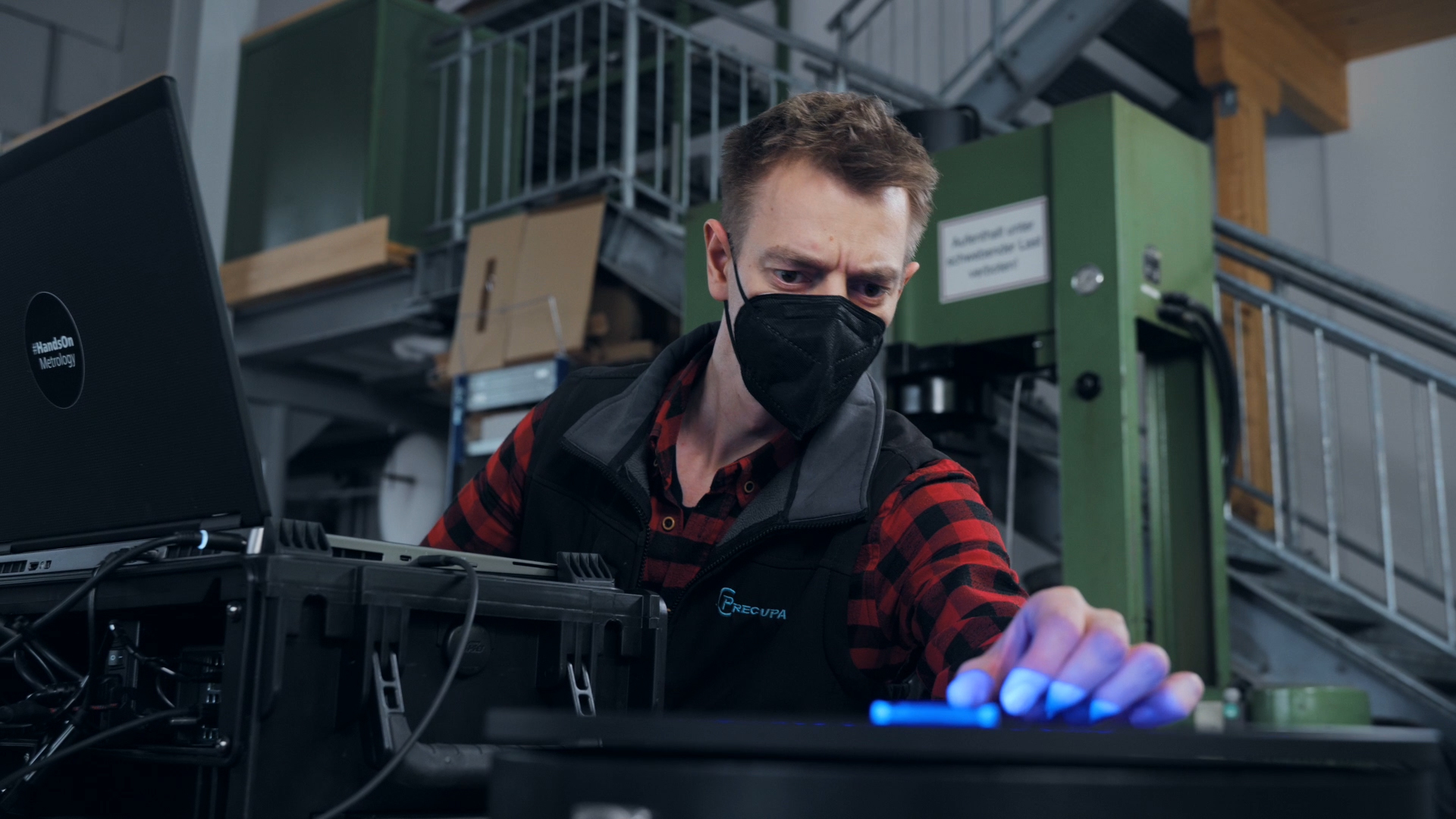
Precupa: Looking to a more sustainable future
Operating for over 40 years at the foot of the Alps, Bavarian firm Precupa builds injection molds for the plastic industry. Together with his team, managing director Thomas März is constantly looking for ways to incorporate innovative and sustainable new technologies, such as Zeiss Reverse Engineering, into Precupa’s workflow. Our Maker Portraits are behind-the-scenes looks at some of the most exciting manufacturing, maintenance and repair service workshops.
Want to learn more about Precupa? Visit www.precupa.de
Fraunhofer IWU: Unique solutions for unique tasks
At the Fraunhofer Intitute for Machine Tolls and Forming Technology, there is no „normal business“. Instead, it’s all about unique clients with unique tasks seeking unique solutions. Whether it’s in the automotive, medical or robotics industry: 3D scanning makes it possible to step into the future – every day.
More information about our handheld systems, go to Getting Started T-SCAN hawk 2.
Atka: The plastics specialists
At Atka, it’s all about plastics. And about machines that attach non-manipulable plastic caps to beer kegs and are delivered to breweries all over the world. 3D scanning enables this family-run business to stay ahead of the game at all times.
Bereit für die Rennstrecke: Rallye mit BMA Autosport
fischer group: Stahlrohre jenseits des Standards
Stahlotec: Retrofit für Stahlkolosse
Formlabs: Mit 3D-Druck in die Zukunft
Cowboy: Vernetzte E-bikes für urbane Pendler
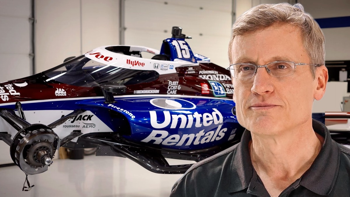
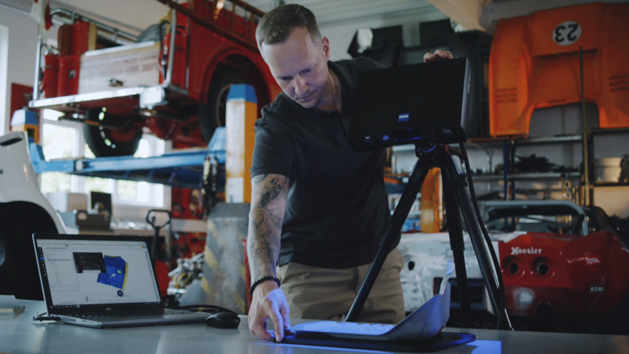
RLL Racing: Technology wins races
Take a look behind the scenes at Rahal Letterman Lanigan Racing as they are getting their cars ready between races at the IndyCar Series. 3D scanning helps the team to modify their cars‘ bodyparts in order to maximize downforce, minimize drag and improve performance.
More information about our handheld systems, go to Getting Started T-SCAN hawk 2.
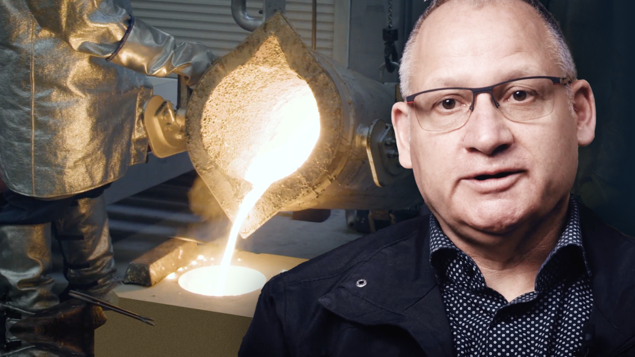
HA Group: Die Zukunft der Gießerei
R.A.R. Antwerpen: Gut ist niemals gut genug
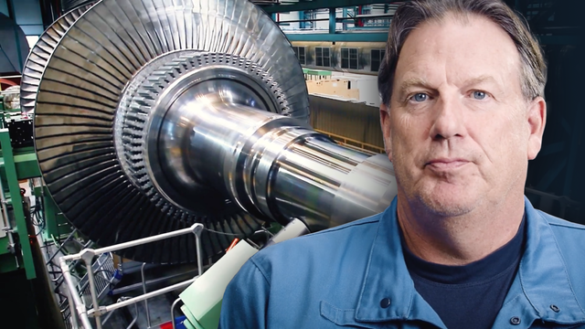
Energetic: Die Magie der Turbinen
Fagus: Leisten für die internationale Schuhindustrie
MMG: Meet the world’s largest ship propellers
Meet MMG and their impressive ship propellers. Although huge, the parts are planned to the detail before months of development culminate in about ten minutes of casting time. To ensure quality and functionality, 3D measurement plays an import role in the process. Be ready for a big story.
Our Maker Portraits are behind-the-scenes looks at some of the most exciting manufacturing, maintenance and repair service workshops. Do you want to learn more about MMG? Visit www.xxl-metalworking.com
SST Flugtechnik: Flugzeugdesign made in Germany
One-Minute Insights
One 3D scan is all you need for precision
You’re new to 3D scanning? You think that scanning across the same area several times igenerates better data? It’s a typical scanning rookie misconception, says Marco, and one that can be easily avoided. One scan is all you need for perfect results.
Have you got any questions about 3D scanning? Then contact us via email: support@HandsOnMetrology.com
ZEISS INSPECT: Less mouse miles with a customized toolbar
Learn how to reduce your mouse mileage by customizing your toolbar. You want to use the software for reverse engineering? Daniel suggests adding Select Patch, Close Holes and Export STL to your bar – for a more intuitive, faster 3D scanning workflow.
All functions shown are available in the current software version.
Do you have any questions about ZEISS INSPECT? Contact us via email: support@HandsOnMetrology.com
How to use ZEISS INSPECT as a presentation viewer
Get an insight from Jonas and learn why he prefers to use ZEISS INSPECT as a viewer whenever he has to present the results of an inspection job to a client or the team.
All functions shown are available in the current software version.
Have you got any questions about ZEISS INSPECT ? Then contact us via email: support@HandsOnMetrology.com
Cutting objects into pieces with Delete by Plane
Do you want to print a piece of art that is bigger than the volume of your 3D printer? Jurgen from Tetra Vision shows you an easy way to do just that, using the Delety by Plane function in ZEISS INSPECT.
All functions shown are available in the current software version
Have you got any questions about ZEISS INSPECT? Then contact us via email: support@HandsOnMetrology.com
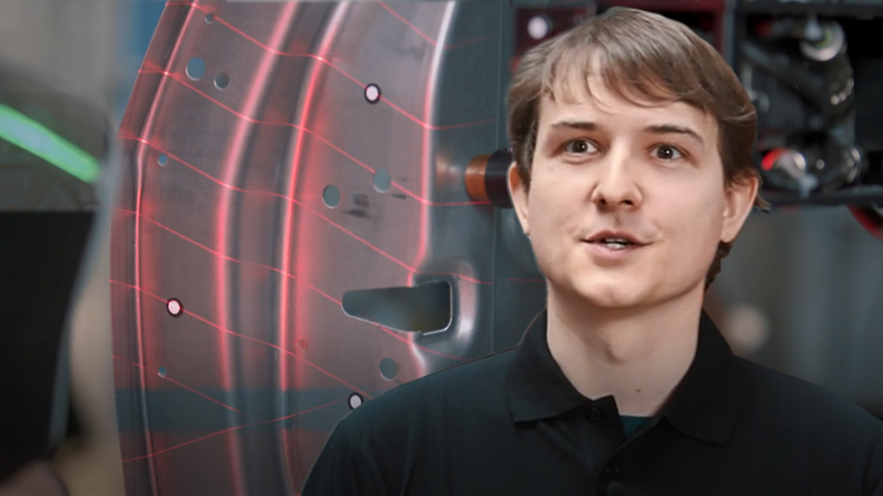
Visualize 3D deviation using isolines
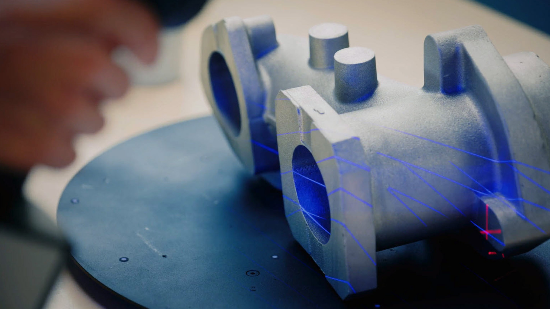
You want to see exactly which areas of a 3D scan are in and out of tolerance? Discover deviations at a glance – by doing a surface comparison and using your 3D scanner to project the isolines directly onto the part. Have you got any questions about 3D scanning? Then contact us via email: support@HandsOnMetrology.com
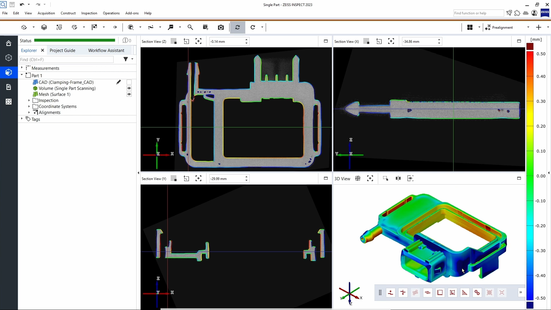
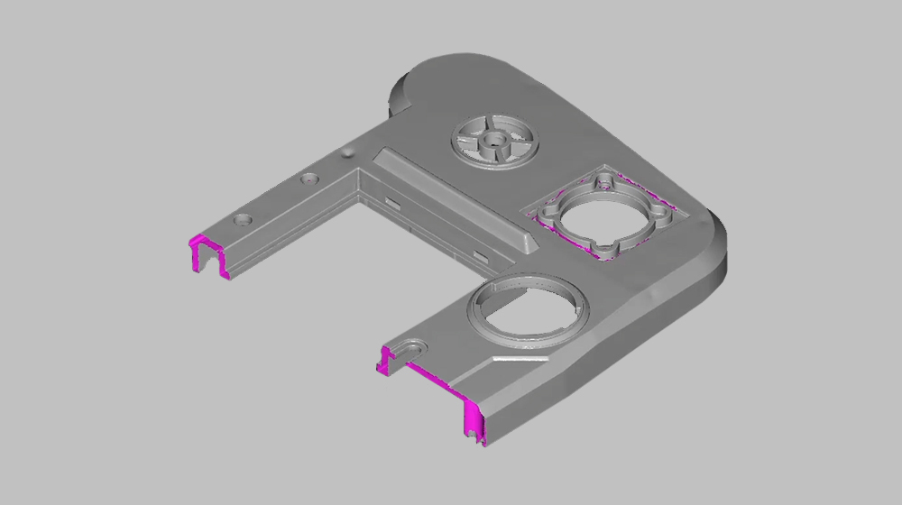
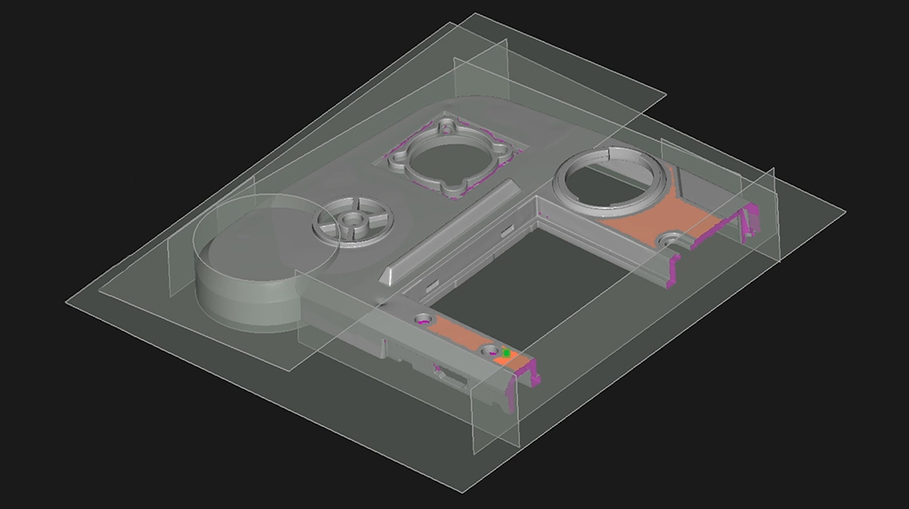
Use the Clipping Cube function to get a perfect view
Zeit sparen mit Quick GD&T
Erhalten Sie einen One Minute Insight von Christine, Carl Zeiss GOM Metrology Braunschweig. Sie zeigt Ihnen, wie Sie mit einem einzigen Klick auf „Quick GD&T“ viele Mauskilometer sparen können, um eine besonders schnelle Toleranzprüfung zu erhalten. Alle gezeigten Funktionen sind in der aktuellen Softwareversion verfügbar.
Haben Sie Fragen zu ZEISS INSPECT? Dann kontaktieren Sie uns per E-Mail: support@HandsOnMetrology.com
Data import from 3rd party scanners
3D scan like a pro without a rotation table
You’re starting out in 3D scanning and don’t have a rotation table (yet)? Don’t worry. Follow Daniel’s easy approach to scanning without one: Simply scan the part in eight steps, turning it by 45° between each scan.
All functions shown are available in the current software version.
Have you got any questions about 3D scanning? Then contact us via email: support@HandsOnMetrology.com
Reduce mouse miles with the Smart Creation button
Some 3D inspection projects involve creating a lot of elements – and a lot of mouse miles. Avoid moving your mouse to „Create“ over and over again by using the Smart Creation button directly under your mouse pointer.
All functions shown are available in the current software version.
Have you got any questions about GOM Inspect? Then contact us via email: support@HandsOnMetrology.com
Wie man große Objekte mit einem tragbaren 3D-Scanner scannt
How does satellite mode work and why do you need it
Scanning larger parts can be challenging. We simplified the the process with the new satellite mode of the handheld laser scanner ZEISS T-SCAN hawk 2. It does without coded markers thus preparations are easy and fast. Learn more about the advanced way of photogrammetry here. Got any questions? Contact us via support@HandsOnMetrology.com.
GOM Scan 1
GOM Scan 1: Unboxing
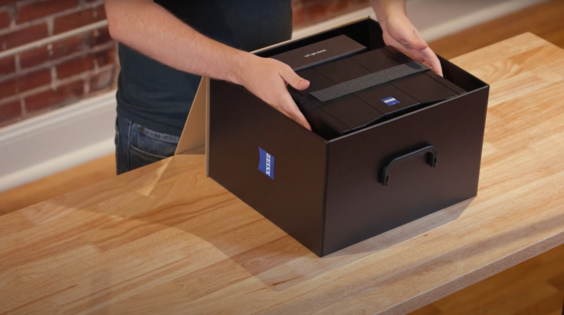
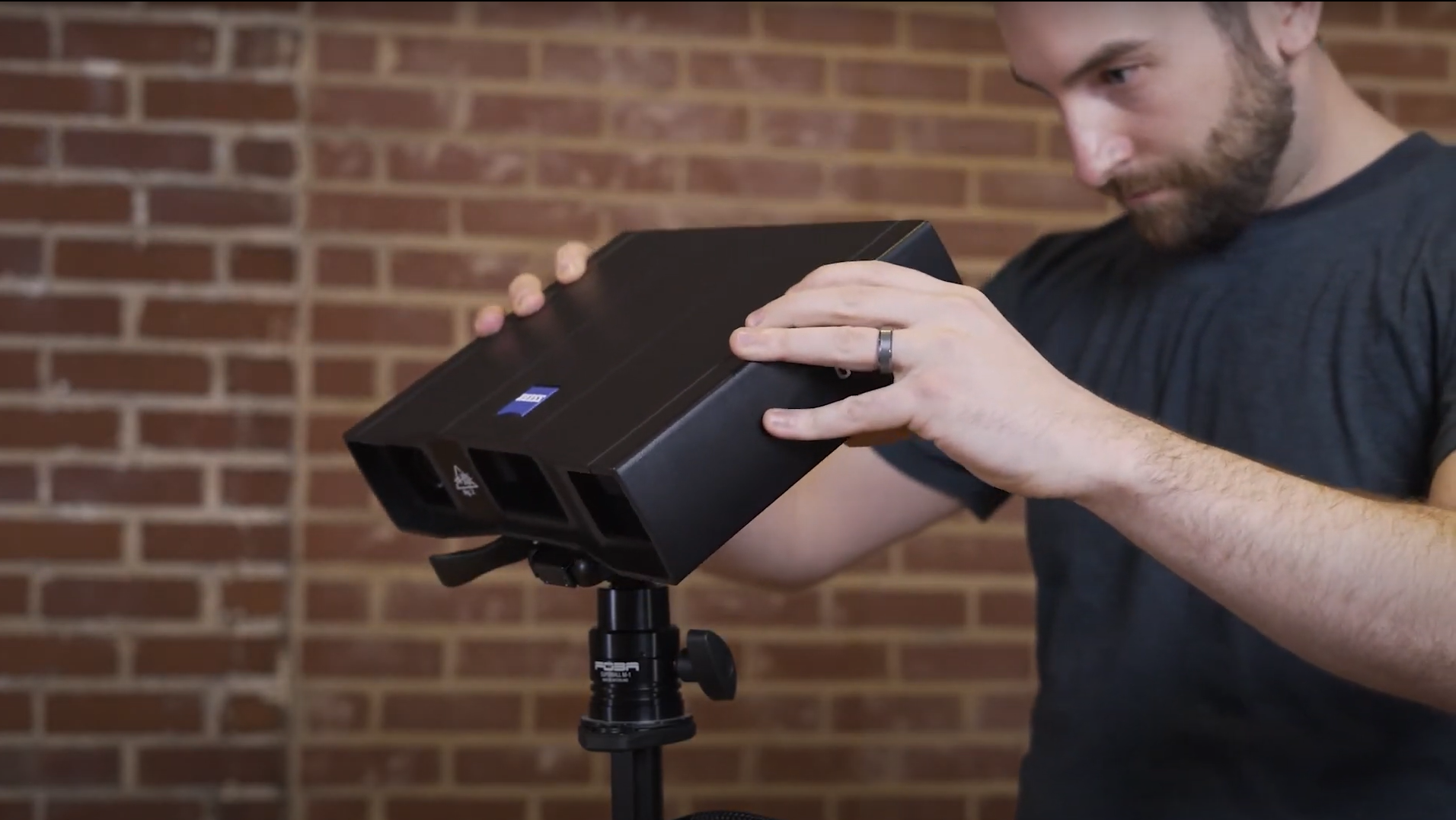
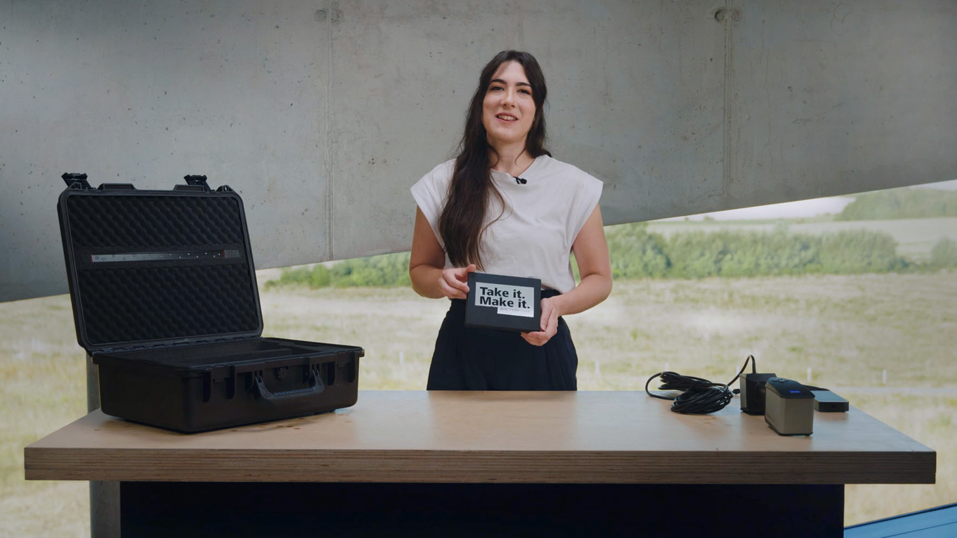
Watch Miles unbox the GOM Scan 1. What’s included: the sensor, a sensor cable, a power adapter and a measuring plate, a calibration object holder, a calibration panel and a useful accessories box. For those who travel a lot: a sturdy travel case is also available, with perfectly sized, padded compartments for all GOM Scan 1 elements, a tripod and an automatic rotation table.
GOM Scan 1: Das Setup
GOM Scan 1: Calibration
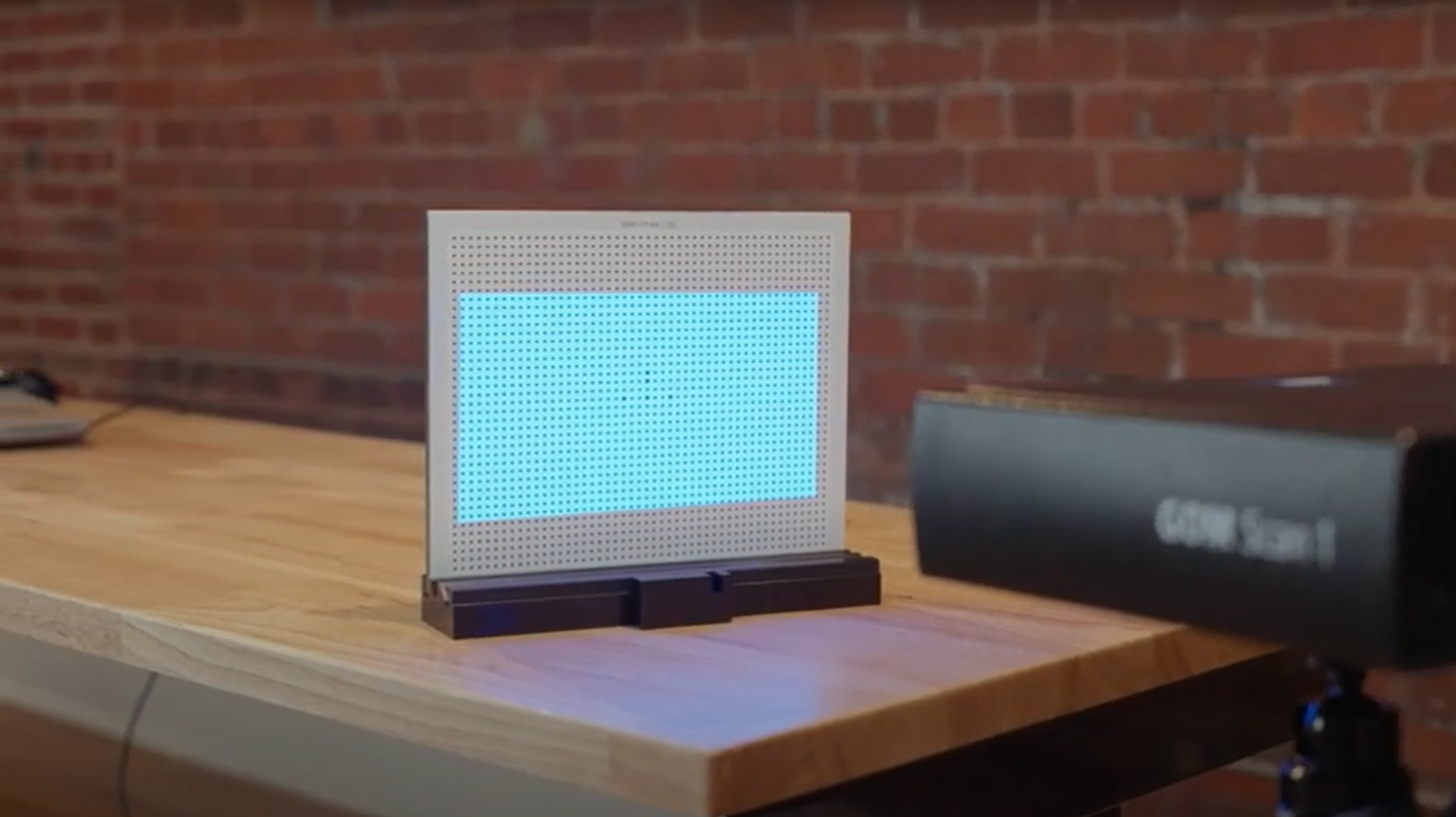
Calibrating your GOM Scan 1 is easy! Let Miles show you how it’s done. The GOM Scan 1 comes with all the accessories necessary for calibration – the software GOM Inspect guides you through the process and takes care of the rest. The best part: The sensor detects automatically, when it has to be recalibrated and informs you about it.
GOM Scan 1: Die Wahl des richtigen Sensors
GOM Scan 1: Deine erste Nutzung von ZEISS INSPECT
GOM Scan 1: Einführung in die Bauteilinspektion
GOM Scan 1: Scanning Multiple Parts
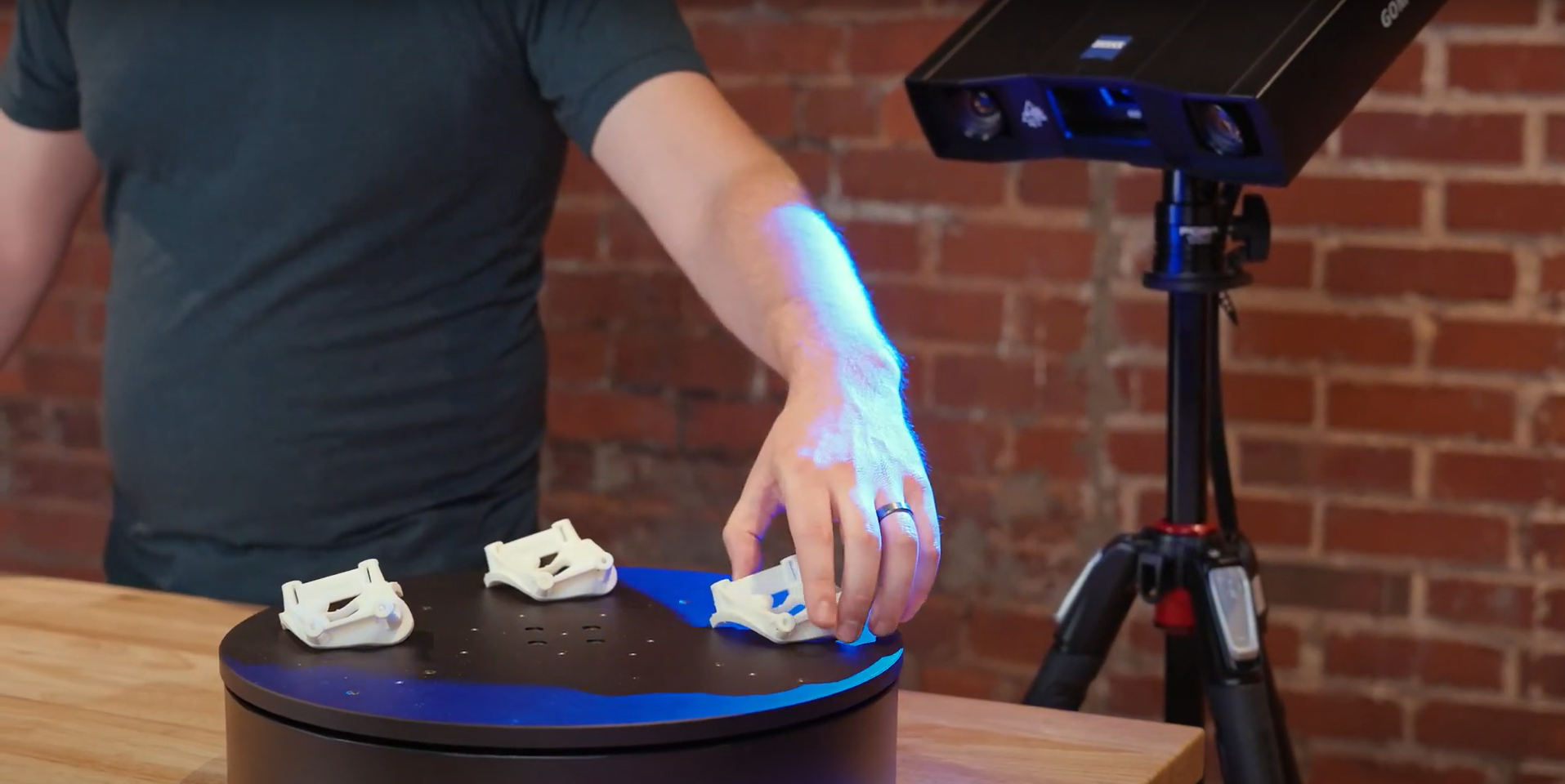
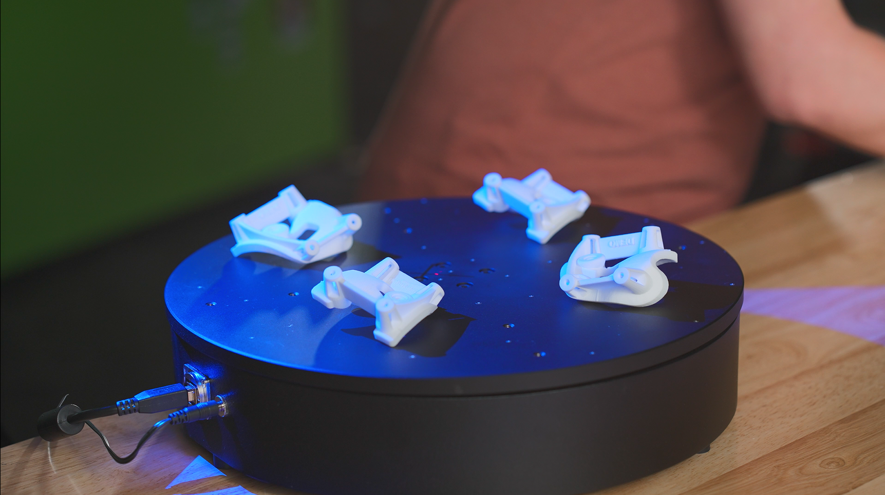
Let Miles show you how to scan multiple identical parts simultaneously using the GOM Scan 1 400 and the rotation table GOM Rot 350. Simply choose the workflow assistant for scanning multiple parts and follow the software as it guides you through the scanning process. Since the rotation table is marked with reference points, you can start scanning straight away. Partitioning the parts and aligning top and bottom scans is done with just a few clicks.
GOM Scan 1 für Reverse Engineering und 3D-Druck
GOM Scan 1: Hochdetaillierte Teile scannen
GOM Scan 1: Oberseiten und Unterseiten scannen
GOM Scan 1: Mit einem Drehtisch scannen
GOM Scan 1: Mit einer Messplatte scannen
How to 3D scan different materials
How to 3D scan with the right distance to object
How to find your perfect exposure time with ZEISS INSPECT
Let Norman show you how to find the perfect exposure time for your part. The live camera image in ZEISS INSPECT offers multiple options of automatic exposure times: automatic by matrix computes up to three different exposure times for the entire field of view – making it a good choice for parts that combine light and dark surfaces. Other options: automatic by spot, automatic for reference points and interactive. Take a pick and start scanning!
All functions shown are available in the current software version.
Got any questions on 3D scanning? Contact us via support@HandsOnMetrology.com
Wie du deine eigenen Ersatzteile scannst & druckst
Wie man eine 3D-Inspektion an einem 3D-Druck durchführt
T-SCAN hawk 2
T-SCAN hawk 2: Unboxing your new 3D laser scanner
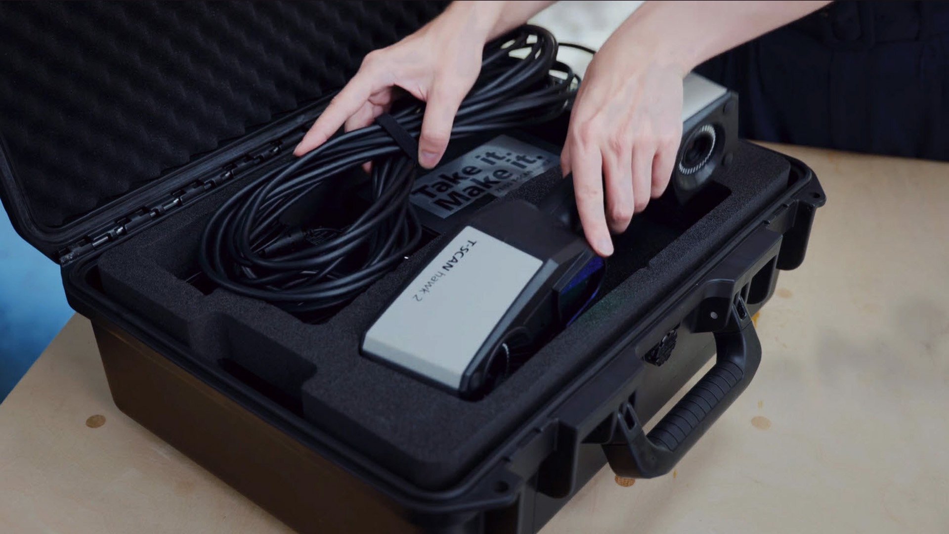
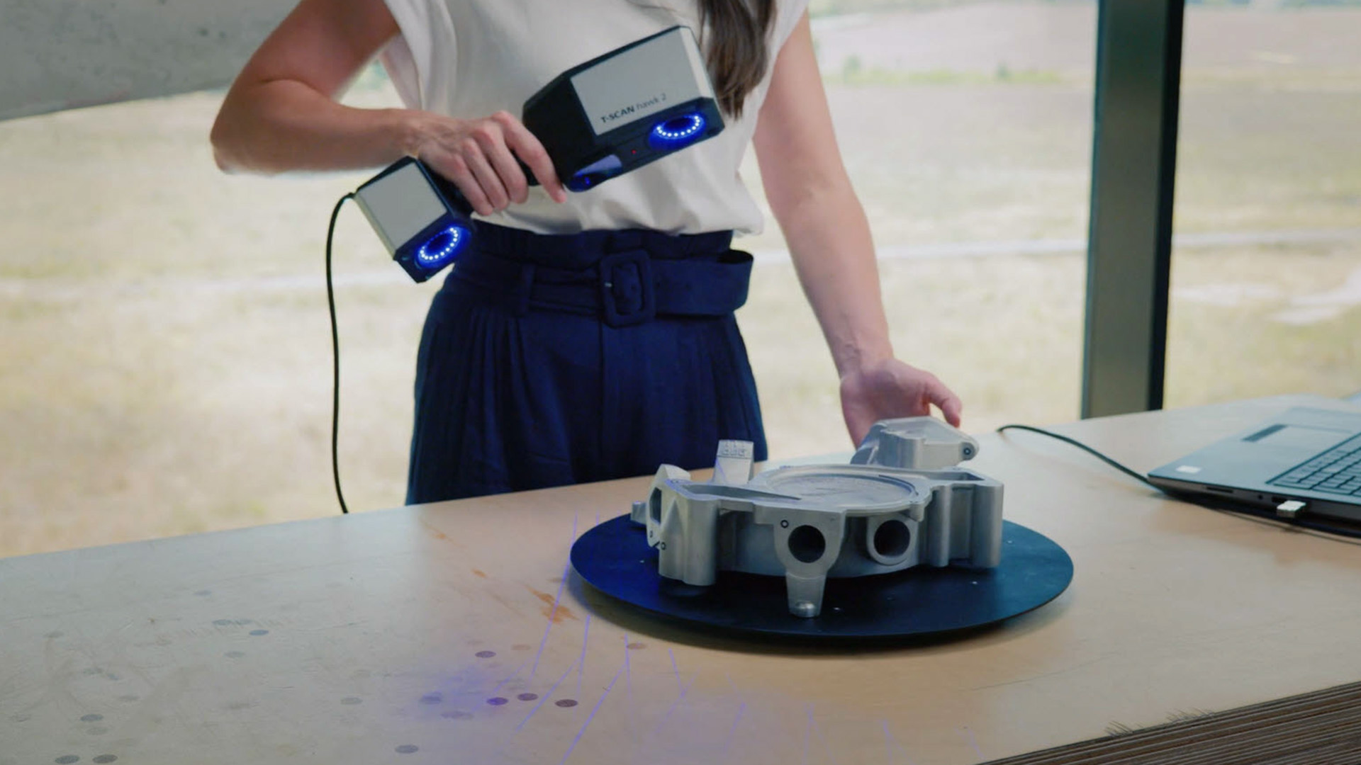
Get started with your T-SCAN hawk 2. In this first episode you get to unbox the new hand-held laser scanner together with Aysel. Whether the power cable, the calibration panel or reference points, we got you covered for easy, fast and precise 3D scanning. Have you got any questions about 3D scanning? Contact us via support@HandsOnMetrology.com
T-SCAN hawk 2: The setup
Want to know what to consider when setting up your new T-SCAN hawk 2? Let Aysel show you an easy step-by-step guide for starting your laptop as well as the system. Get ready for your first scan with the T-SCAN hawk 2! Have you got any questions about 3D scanning? Contact us via support@HandsOnMetrology.com
T-SCAN hawk 2: Your first use of ZEISS INSPECT
In our Getting Started we demonstrate how easy it is to start scanning with the T-SCAN hawk 2. Besides the calibration process, Aysel navigates you through the ZEISS INSPECT software and gives useful tips and tricks for your first scan.
All functions shown are available in the current software version.
Have you got any questions about 3D scanning? Contact us via support@HandsOnMetrology.com
T-SCAN hawk 2: Scanning in ZEISS INSPECT
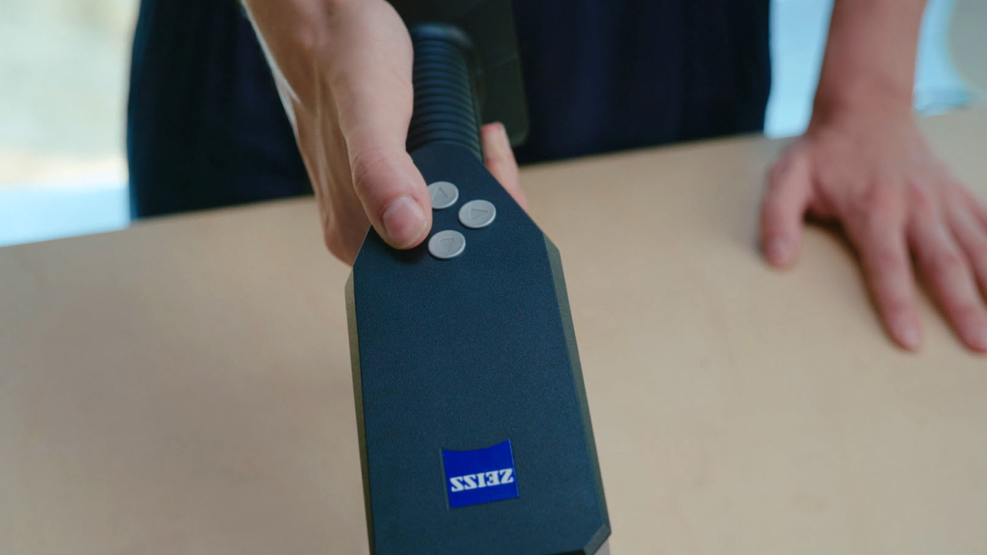
Have a look at the remote workflow which guides you through different scanning task with ease. Aysel applies the common scanning strategy of scanning one side of the part only. The buttons on the backside of the scanner simplify the process, even when scanning deep pockets.
All functions shown are available in the current software version.
Got a question? Contact us via support@HandsOnMetrology.com
T-SCAN hawk 2: Scanning with reference points
Have a look at how to easily scan both sides of your part using reference points. With just a push of a button on the T-SCAN hawk 2, the guided workflow assists in the scan. The software optimizes the polygonization of the final mesh. Have you got any questions about 3D scanning? Contact us via support@HandsOnMetrology.com
T-SCAN hawk 2: Scanning without reference points
You are scanning a lot of 3D geometries? Then go ahead and try the scanning strategy Aysel presents in this Getting Started: Scanning without any reference points. Just select the right template in the software, define the background plane and start your 3D scan. Have you got any questions? Contact us via support@HandsOnMetrology.com
T-SCAN hawk 2: The new Satellite mode
In this Getting Started we demonstrate how to accurately scan large parts with photogrammetry. The new integrated satellite mode ensures precise pre-referencing. No other features, like coded markers, are necessary. Watch the video to see the T-SCAN hawk 2 unleash its full potential.
Do you want to find out more about the portable 3D laser scanner T-SCAN hawk 2? Visit HandsOnMetrology.com/sessions
T-SCAN hawk 2: Scanning fine details
Whether you are scanning large parts with local details or a completely detailed part, T-SCAN hawk 2 is the right solution. Let Aysel explain you, how to operate the scanner and get useful tips and tricks for both cases. Have you got any questions? Contact us via support@HandsOnMetrology.com
T-SCAN hawk 2: Scanning deep pockets
Your challenge is to scan deep pockets of a part? The single laser line mode of the T-SCAN hawk 2 allows you to scan even deeper into wholes. Watch the Getting Started to learn more about the detailed scan of hard to reach areas. Have you got any questions on 3D scanning? Contact us via support@HandsOnMetrology.com
T-SCAN hawk 2: All features of the remote control buttons
Let Aysel show you the different possibilities of the control buttons on the back of the T-SCAN hawk 2. It makes starting the remote workflow, zooming in and out, opening the menu and more as easy as a push of the button. Have you got any questions on 3D scanning? Contact us via support@HandsOnMetrology.com
T-SCAN hawk 2: Accessories
You want to scan your parts without sticking reference points on it? We have the right accessory for you: the magnetic reference pillars. Placing them around the part ensures easy, intuitive and accurate data collection. Have you got any questions on 3D scanning? Contact us via support@HandsOnMetrology.com
T-SCAN hawk 2: Get some useful tips & tricks
Need more tricks on the new T-SCAN hawk 2? Aysel is going to reveal useful tips that make your scanning process even more successful. Get more information on topics, like exposure modes, scanner orientation, defining background planes and customizing workflows. Have you got any questions on 3D scanning? Contact us via support@HandsOnMetrology.com
How to scan large parts using ZEISS T-SCAN hawk 2
Looking for an easy and intuitive way to 3d scan large parts up to multiple meter? Then the 3D laser scanner ZEISS T-SCAN hawk 2 with the new satellite mode is the right solution for you. Let Matthias show you how it’s done.
Do you have any questions about ZEISS T-SCAN hawk 2? Contact us via support@HandsOnMetrology.com
How to 3D scanning for fast and efficient incoming inspection in MRO
Keeping equipment in good condition is necessary for an efficient production process. 3D scanning helps to capture all dimensions of parts for a fast inspection. Roel shows you how reparation or modification of equipment can be done using hand-held solutions. Got any questions on 3D scanning? Contact us via support@HandsOnMetrology.com
How to perform fast inspection in electric motorcycle assembly
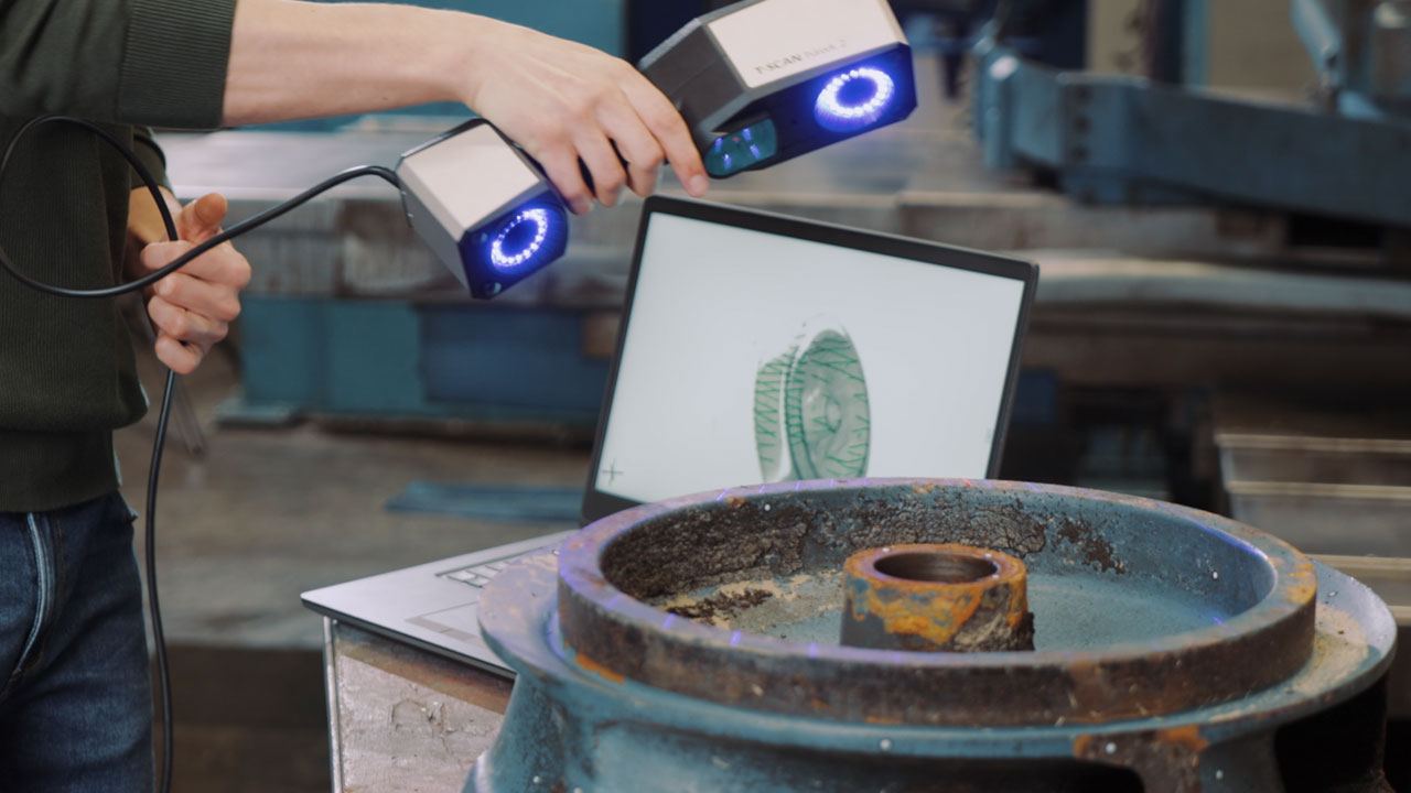
Components with different tolerances, make building safe motorcycles a challenge. Let Alex show you how easy it can be to inspect single motorcycle components and the digital assembly with ZEISS T-SCAN hawk 2 and the inspection software of the ZEISS Quality Suite. Got any questions on 3D scanning? Contact us via support@HandsOnMetrology.com
How to set up a digital warehouse with 3D scanning
3D scanning helps to create your digital warehouse in MRO. With the digital copy you have important information at hand in the event of a sudden defect. Reduce costs due to extended downtime or storage, and easily access your digital inventory where and when you need it. Got any questions on 3D scanning? Contact us via support@HandsOnMetrology.com
How to reproduce unavailable spare parts in MRO
Currently facing the challenge of reproducing unavailable spare parts? 3D scanning might be the solution you need to minimize risky downtime. By capturing the dimensions of the equipment, a reproduction is possible in no time. Watch the How to to learn more about it. Got any questions on 3D scanning? Contact us via support@HandsOnMetrology.com
How to 3D scanning for wear control in MRO
Wear and tear of production equipment causes malfunctioning, delays, downtime. In this How to, Roel shows you how 3D scanning is used to implement predictive maintenance – and therefore keep production running efficiently.
Got any questions on 3D scanning? Contact us via support@HandsOnMetrology.com
How to weld check on electric motorcycle frames
The basic structure of a motorcycle is the welded frame. Weld inspection is therefore necessary not only to maintain quality of parts, but also for customer safety. With the ZEISS T-SCAN hawk 2 and the weld inspection package of the ZEISS Quality Suite, you can easily scan, classify and inspect welds. Let Juan show you how it’s done.
Got any questions on 3D scanning? Contact us via support@HandsOnMetrology.com
How does satellite mode work and why do you need it
Scanning larger parts can be challenging. We simplified the the process with the new satellite mode of the handheld laser scanner ZEISS T-SCAN hawk 2. It does without coded markers thus preparations are easy and fast. Learn more about the advanced way of photogrammetry here. Got any questions? Contact us via support@HandsOnMetrology.com.
How to use a 3D scanner for dent detection
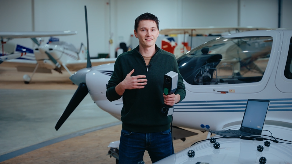
Looking for a way to speed up and refine your aircraft MRO? Let Roel show you how the ZEISS T-SCAN hawk 2 and the Inspect Software aid in various inspection tasks, like GD&T, CAD comparisons or defect maps. Got any questions on 3D scanning? Contact us via support@HandsOnMetrology.com
How to measure in production
Small and portable: the ZEISS T-SCAN hawk 2 is made for the use in production. See here how it supports your complete process chain from data collection for reverse engineering, different inspection tasks to the digital assembly of produced parts.
Do you want to find out more about the portable 3D laser scanner T-SCAN hawk 2? Visit HandsOnMetrology.com/sessions
How to scan large objects using a portable 3D scanner
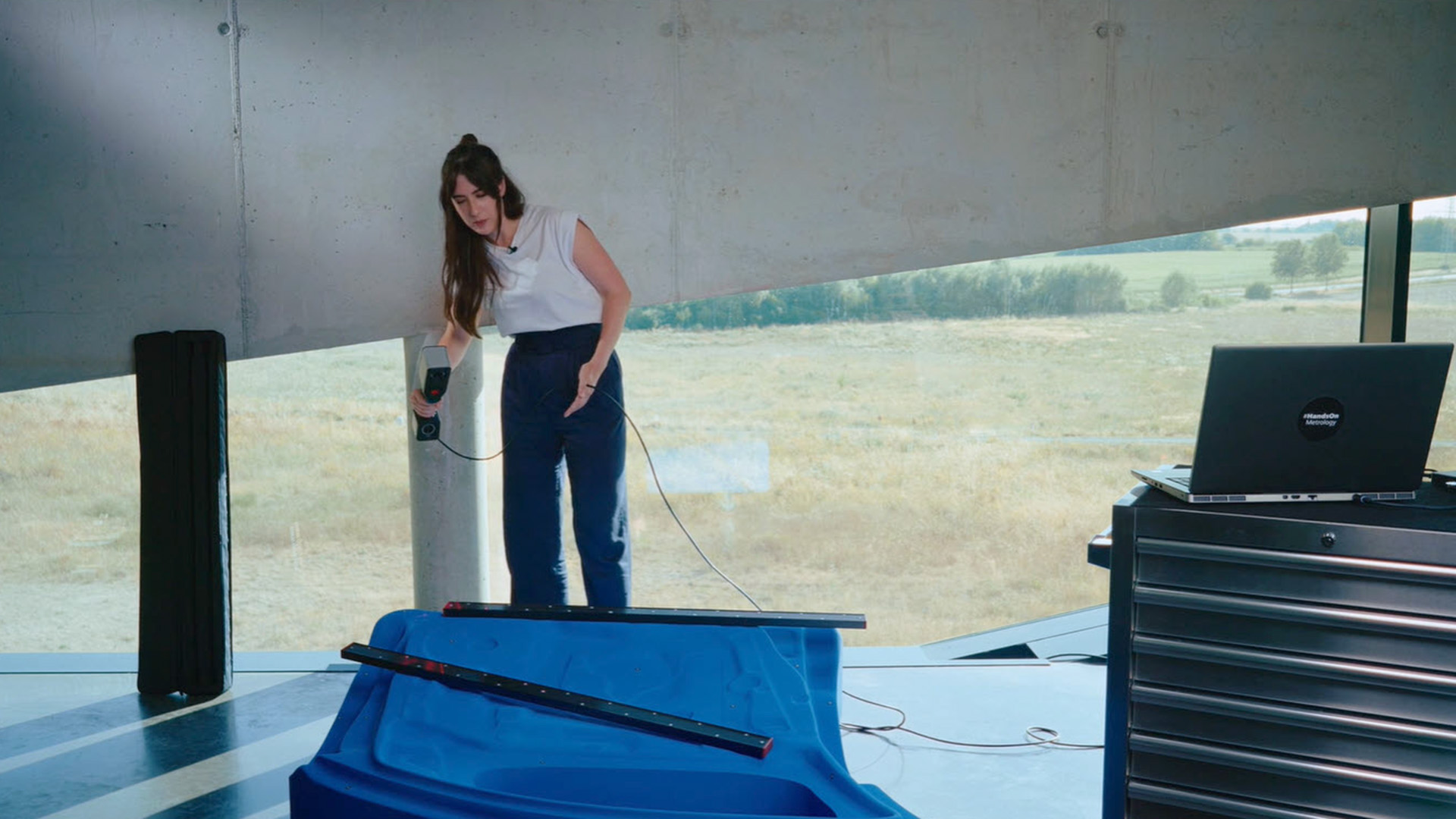
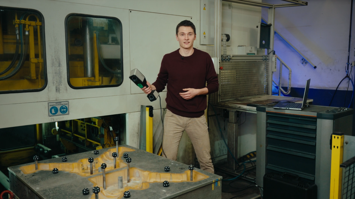
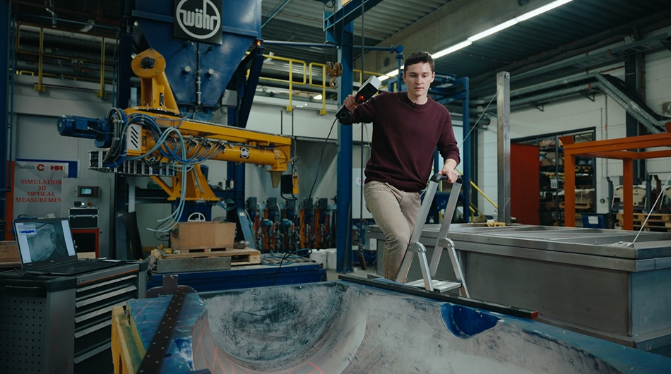
Learn how to measure big parts, like sand molds. Roel is using the new Satellite Mode of the ZEISS T-SCAN hawk 2 – replacing the built-in photogrammtry of the previous scanner generation. Together with scale bars, reference points and the big field of view of the handheld sensor, it is a powerful combination which ensures highly accurate data.
How to use a 3D scanner in confined spaces
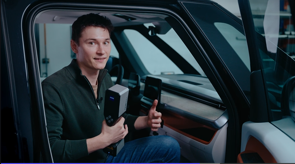
In this How to Roel is scanning complex and hard to reach areas of a van interior. Whether for inspection or design purposes – the ZEISS T-SCAN hawk 2 is the perfect fit for extracting accurate and complete dimensions in confined spaces. Got any questions on 3D scanning? Contact us via support@HandsOnMetrology.com
ATOS Q
ATOS Q: Zu einem kleinen Messvolumen wechseln
ATOS Q: Start a project in ZEISS INSPECT
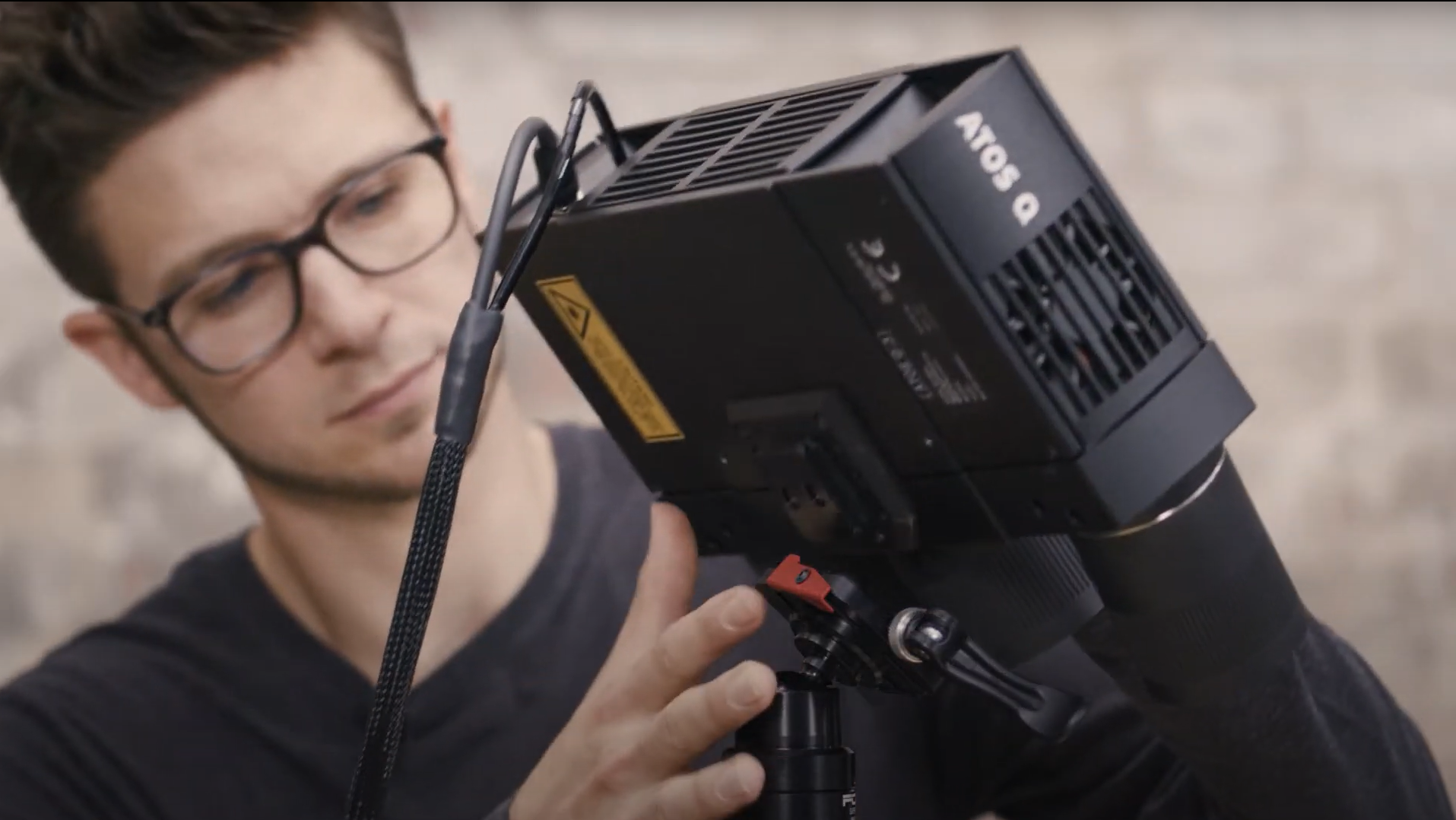
Let Dokus show you how to make your first scan with ZEISS INSPECT. He takes you from the start screen to the checkered flag: a very detailed mesh. See different workspaces and scanning templates. Learn how to scan and watch what happens when you rotate the table.
All functions shown are available in the current software version.
Got any questions on 3D scanning? Contact us via support@HandsOnMetrology.com
Chapters
00:42 Start software
01:03 Workspaces
01:33 Digitizing workspace
01:58 Main toolbar
02:22 First scan and cut out background
02:50 Reference points
03:18 Polygonize and recalculate
ATOS Q: Unboxing your new 3D scanner
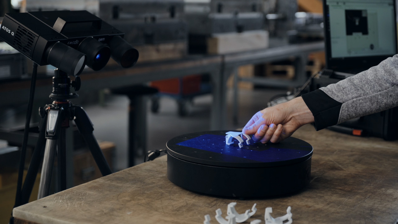
Meet Dokus and the ATOS Q with its two cases. The first case contains the ATOS Q sensor and everything you might need on location, from rotation table to measuring volumes or the calibration plate. The second, smaller case contains the laptop and the mobile controller.
Chapters
00:27 The case
00:50 First compartment level
01:05 Second compartment level
01:26 Bottom compartment level
01:34 Mobile controller
01:52 The laptop
ATOS Q: Das Einrichten des Systems
ATOS Q: How to measure big parts
Use the 3D scanner ATOS Q to scan a large part with the measuring volume MV500. Even if the object is bigger than the measuring volume, you can capture it easily using reference points and stitching scans to get a high quality result including small details.
Chapter:
00:42 Start new project and perform first scan
01:24 Stitching scans with reference points
02:01 Finish scan
ATOS Q: How to measure top and bottom of a part
In this video, Dokus measures a part from the top and the bottom side to create a digital twin. A fast and easy workflow with the 3D scanner ATOS Q, assisted by the automatic rotation table and GOM Inspect. After measuring, simply combine and polygonize the data.
Chapters
00:38 Start new project
00:54 Use rotation table
01:38 Flip over the part
01:55 New measurement series
02:42 Combine top and bottom
03:23 Polygonize and recalculate
ATOS Q: Measure with the automatic rotation table
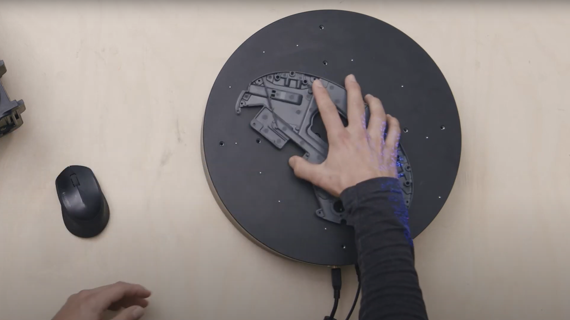
Learn how to use the automatic rotation table to speed up the 3D scanning workflow with ATOS Q. GOM Inspect allows you to choose the number of automatic rotations. A rule of thumb: With 8 rotations you capture almost every aspect of the part.
Chapters
00:45 Rotate rotation table
01:14 Select scanning template and perform first scan
01:41 Use rotation table
02:20 Polygonize and recalculate
ATOS Q: Add single points with a touch probe
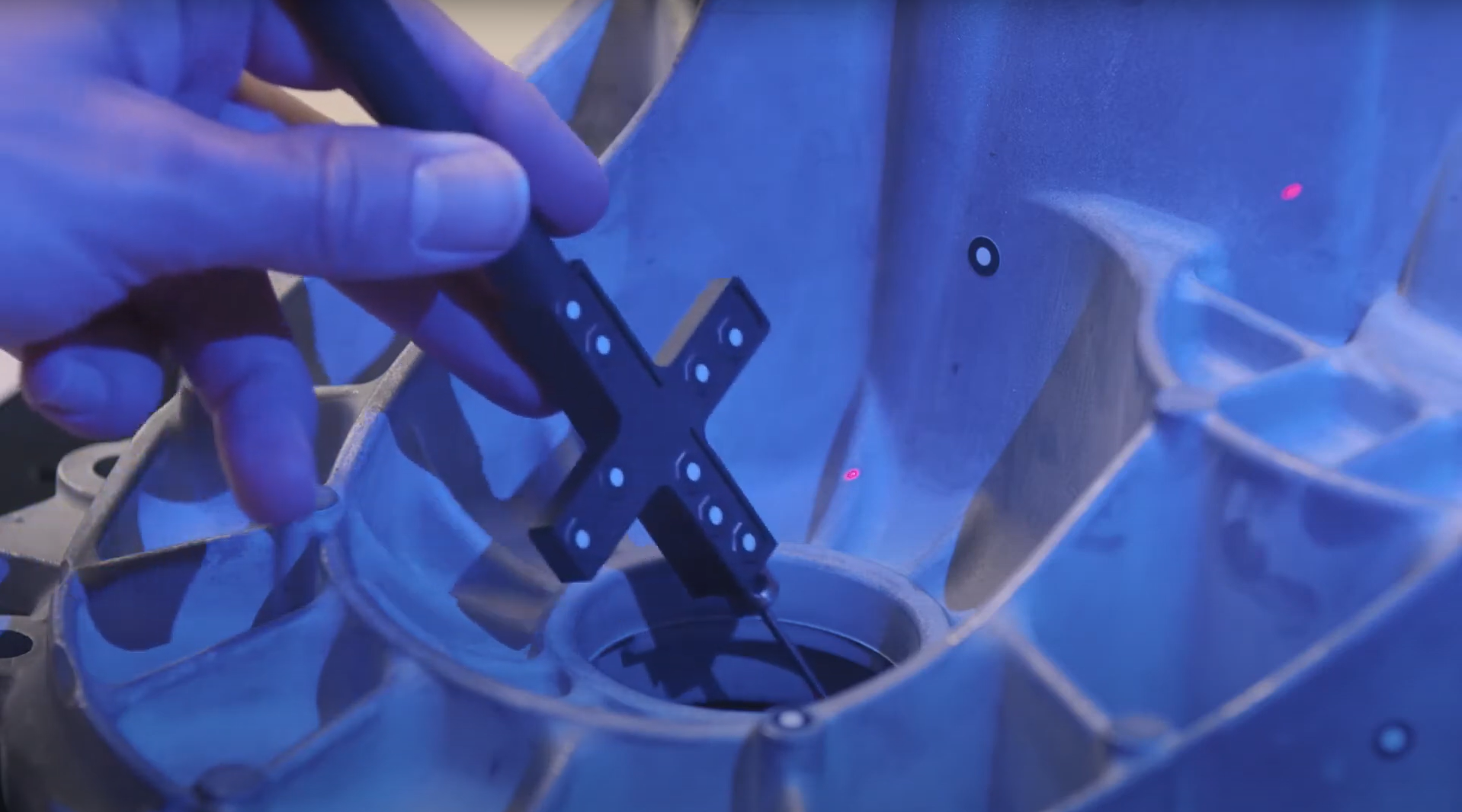
Learn how to use a touch probe to capture 3D data. Dokus shows you how to scan in difficult-to-reach areas and explains guided touch probe measurements in GOM Inspect Suite.
Chapters
00:27 The touch probe
00:49 Live workspace
01:16 Select touch probe
01:44 Finish measurement
02:00 Guided touch probe measurements
02:42 Start guided touch probe measurements
ATOS Q: Tips & tricks to scan even faster
Dokus gives valuable tips on using the 3D scanner ATOS Q. Learn how to measure the automatic exposure time and move the focus point, how to change into fast scan mode – if you don’t need details – or how to manually cut out points.
Chapters
00:42 Automatic exposure time
00:59 Move the focus point
01:36 Fast scanning
02:22 Cut out points
02:52 Selection tools
ATOS Q: Fast inspection with GOM Inspect
How to save time with ZEISS INSPECT
Let Matt show how quality control becomes more efficient using the full version of ZEISS INSPECT. Whether inspecting one or multiple parts, templates transfer pre-made inspection steps in one click. Trend project function furthermore helps when all parts need to be checked at once – making evaluation fast, easy and intuitive.
All functions shown are available in the current software version.
Got any questions on 3D scanning? Contact us via support@HandsOnMetrology.com
How to 3D scan multiple parts with ATOS Q
Learn how to scan multiple identical parts simultaneously using the ATOS Q and a rotation table. Simply choose the workflow assistant for scanning multiple parts and follow the software as it guides you through the scanning process. Since the rotation table is marked with reference points, you can start scanning straight away. Partitioning the parts and aligning top and bottom scans is done with just a few clicks.
Do you have any question on our 3D scanners? Contact us via support@HandsOnMetrology.com
How to eliminate plastic warpage in Quality Control
Annoyed about plastic warpage and how it makes quality control of unassembled parts difficult? In this video, Toon shows you how to solve this problem: with the De-warp function that can be found in the full version of ZEISS INSPECT . It puts scanned plastic parts into a virtually assembled state, allowing you to check their dimensions as if they were assembled.
All functions shown are available in the current software version.
Got any questions on 3D scanning? Contact us via support@HandsOnMetrology.com
So funktioniert der digitale Zusammenbau in ZEISS INSPECT
Wie man Objekte ohne Referenzpunkte scannt
Schnellere 3D-Scans mit einem automatischen Drehtisch
How to get even more out of your ATOS Q
Let Dokus show your the benefits of upgrading your ATOS Q with ZEISS INSPECT – Pro Line: The software offers a wide range of extra features for analysis and inspection and improved functionality. Three of the powerful add-ons are:
1) the use of a touch probe with your system to combine scanning and probing.
2) the use of your system as a live tracking device.
3) the use of your system as a projector – to project elements directly onto the part.
Wie man 3D-Scans für den Bau von Rallyewagen nutzt
METROTOM 1
METROTOM 1: The Setup
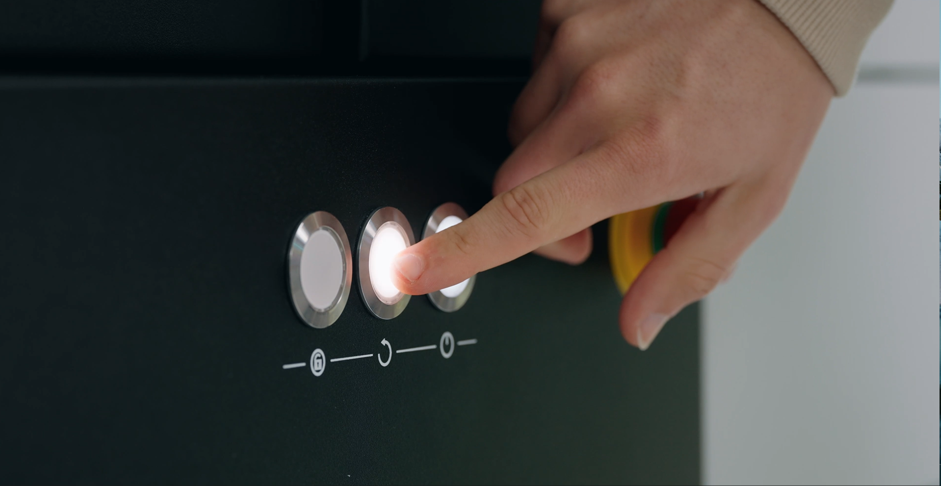
The 3D scanner ZEISS METROTOM 1 is powered by CT technology and allows you to inspect internal structures that can’t be detected with tactile or optical measuring systems. Sounds interesting? In this Getting Started video Aysel and John will teach you how to set up the hardware. Find out how to power up. Discover the scanner’s control hardware with all its switches, buttons and functions. Then learn how to connect the solution to the software ZEISS INSPECT and warm up the X-ray tube.
Have you got any questions on 3D scanning?
Contact us via support@HandsOnMetrology.com
METROTOM 1: Easy part fixture
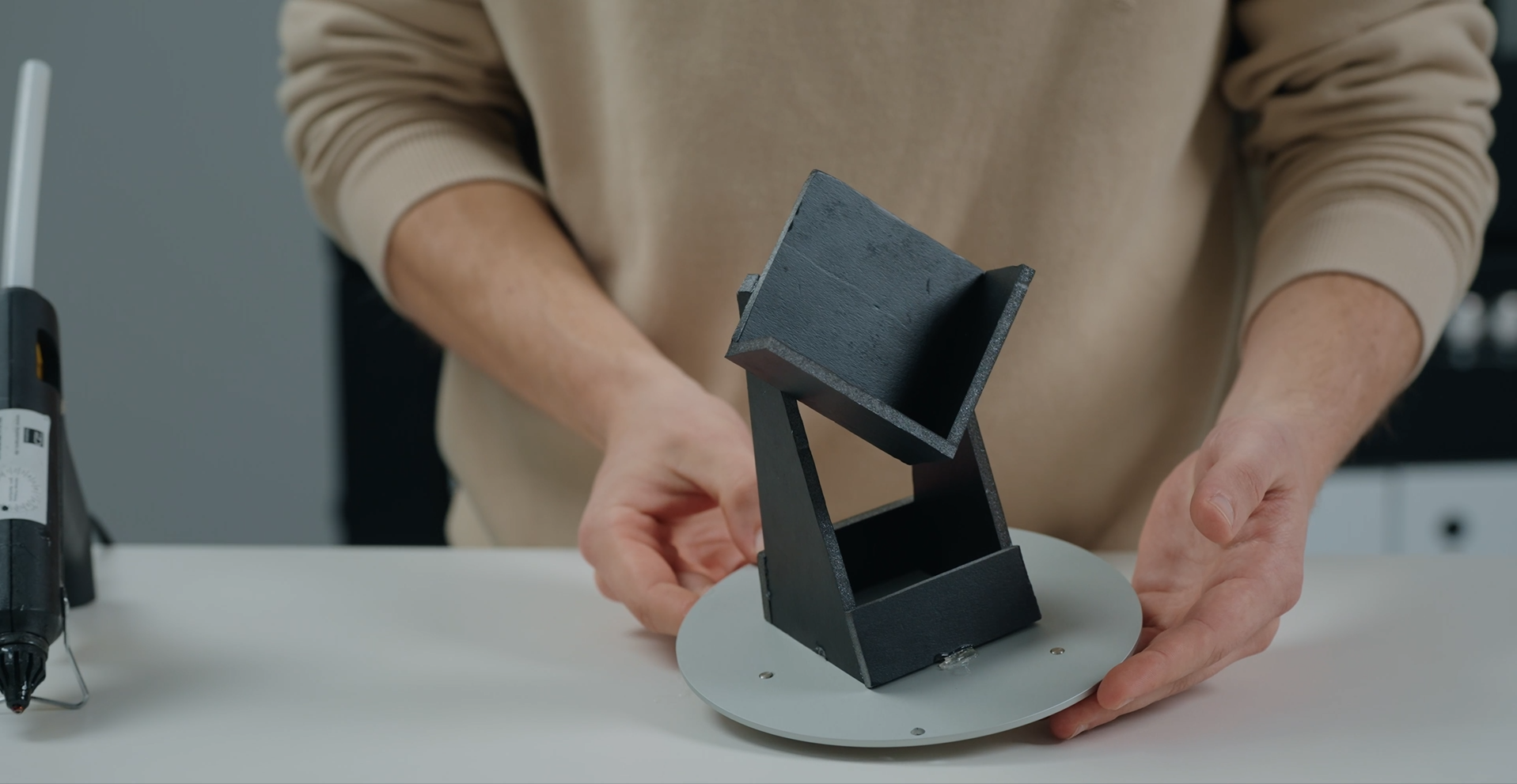
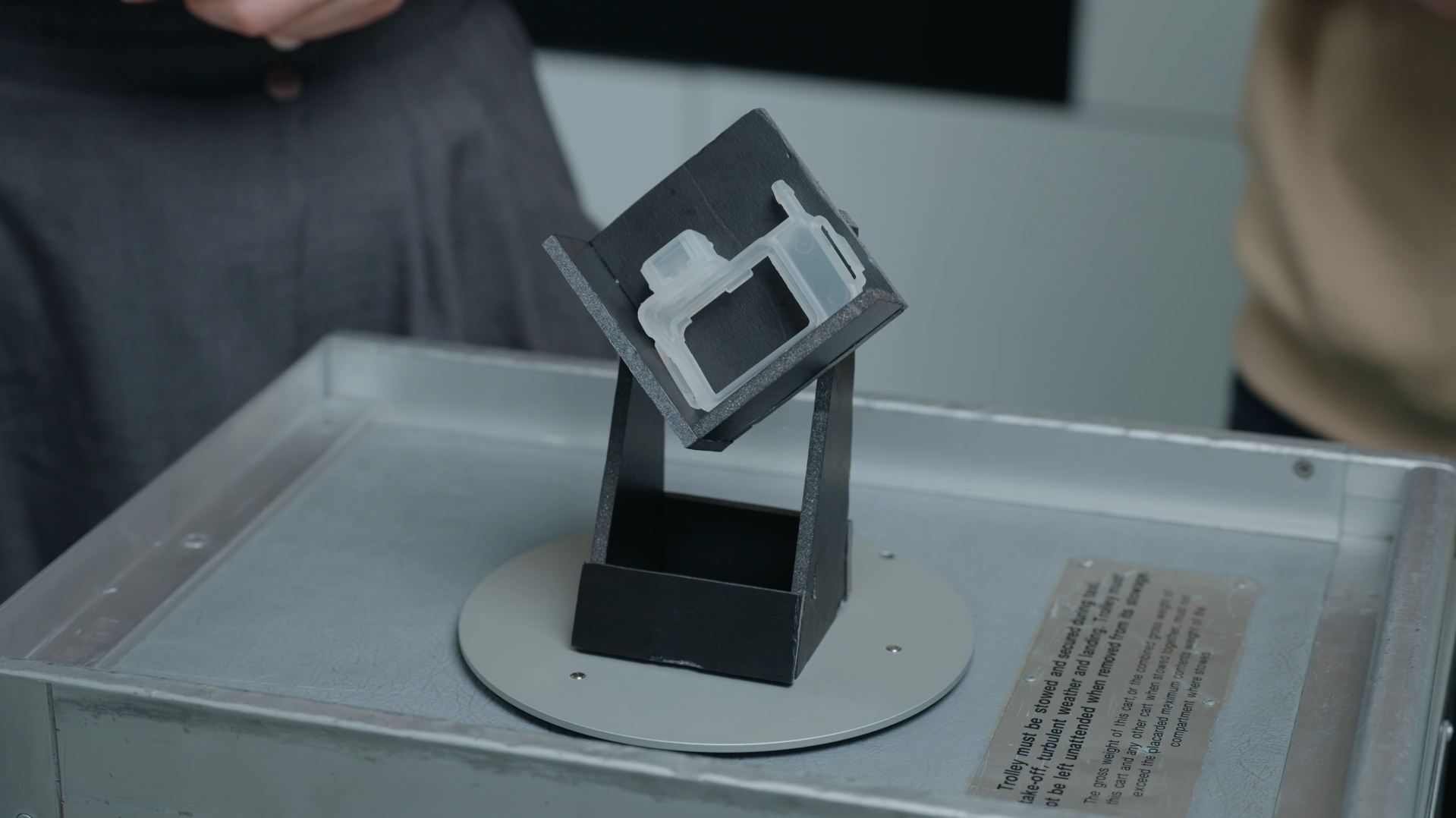
So you got yourself the 3D scanner ZEISS METROTOM 1 – powered by CT technology – and want to learn how to fix a part so it won’t move during the scan? In this Getting Started video Aysel and John will show you a few quick and cost-efficient tricks for creating the perfect part fixture. Watch the two 3D experts as they get crafty with insulation foam and hot glue before placing their part on the fixture plate and locking it into the rotation table inside the system.
Have you got any questions on 3D scanning?
Contact us via support@HandsOnMetrology.com
METROTOM 1: Introduction to ZEISS INSPECT
ZEISS METROTOM 1 – powered by CT technology – is yet another 3D scanning solution that fully reaches its outstanding potential once connected to the software ZEISS INSPECT. Follow Aysel and John, as they take you into ZEISS INSPECT via the ZEISS Quality Suite, and get a quick tour around the four different workspaces, dedicated to scanning, inspecting, reporting and mesh editing.
Have you got any questions on 3D scanning?
Contact us via support@HandsOnMetrology.com
METROTOM 1: Quick & easy calibration
In this video, Aysel and John will show you how to calibrate the 3D scanner ZEISS METROTOM 1. The solution comes with a calibration object and fixture device so you can recalibrate at any time. Good news: The software ZEISS INSPECT guides you through the process. After that, your METROTOM 1 is ready for 100 % accurate 3D scanning.
Have you got any questions on 3D scanning?
Contact us via support@HandsOnMetrology.com
METROTOM 1: Scanning single parts
You want start your first 3D scan with ZEISS METROTOM 1 so you can inspect the internal structures of a part via CT technology? Then watch Aysel and John’s Getting Started video first: Their step-by-step tutorial takes you through the basic scanning strategy of scanning a single, transparent plastic part. You’ll learn about all the adjustments to be made on the METROTOM 1 before the scan – including the adjustment of the filter wheel and the x-ray tube parameters voltage, power and exposure time. Just follow them along – it’s easy.
Have you got any questions on 3D scanning?
Contact us via support@HandsOnMetrology.com
METROTOM 1: Scanning multiple parts
The 3D scanner ZEISS METROTOM 1 – powered by CT technology – is perfect for scanning multiple parts at once, as it seriously reduces scan times. Interested? Then watch Aysel and John’s tutorial. Learn how to prepare the parts for 3D scanning, discover how to set up the software – and experience its simple, built-in separation tool: for separating out the batch volume into smaller volumes for each individual part.
Have you got any questions on 3D scanning?
Contact us via support@HandsOnMetrology.com
METROTOM 1: Easy volume visualization
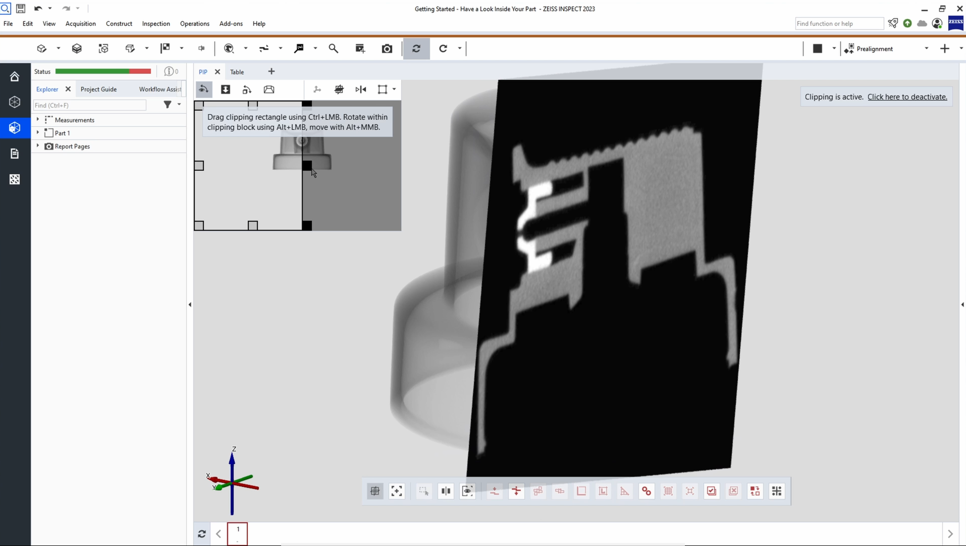
When combined with the software ZEISS INSPECT, the 3D scanner ZEISS METROTOM 1 offers incredible advantages for the inspection of internal defects – and John and Aysel know all the visualization tricks. Follow their tutorial to learn about slicing through a part in order to look inside. Scroll through parts with the clever picture-in-picture view. Choose the multi-view function for a view of all three directions. And get several insights at a single glance by making the mesh and CAD visible, too.
Have you got any questions on 3D scanning?
Contact us via support@HandsOnMetrology.com
METROTOM 1: Easy internal defect inspection
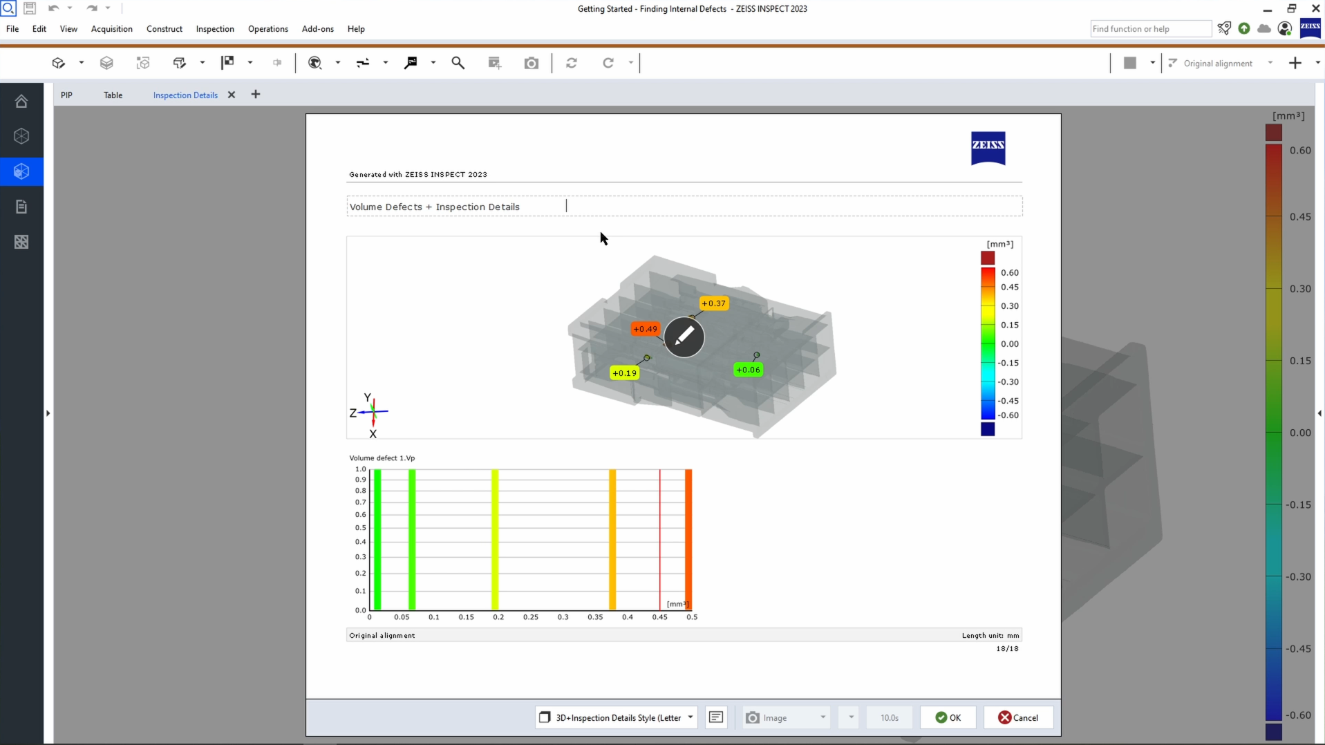
You’re looking for a solution to help you locate and classify internal part defects? Then ZEISS METROTOM 1 – powered by CT technology – is the perfect solution and this video teaches you how it’s done. Learn how to do automated, high-quantity internal inspections on the digital twin of any part. Take a look at all aspects of a defect – from porosity percentage or defect volume to defect length or defect distance to the surface of the part.
Have you got any questions on 3D scanning?
Contact us via support@HandsOnMetrology.com
METROTOM 1: Automated parameter selection
What makes the use of your 3D scanner ZEISS METROTOM 1 even more convenient? Automated parameter selection: a standard function in ZEISS INSPECT. Sounds interesting? In this video you’ll learn how to let the solution calculate suitable parameter settings for you – based on part shape, thickness, density and desired scan resolution. Time for you to sit back and wait for the magic to happen.
Have you got any questions on 3D scanning?
Contact us via support@HandsOnMetrology.com
METROTOM 1: Introduction to scan resolution
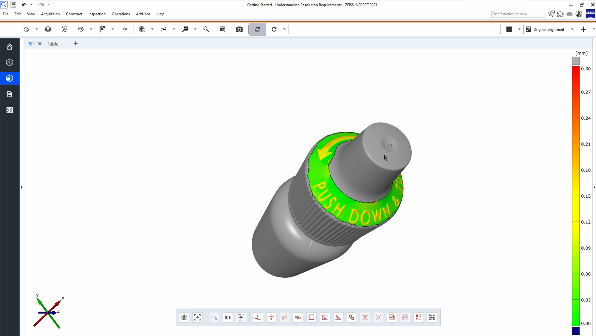
The 3D scanner ZEISS METROTOM 1 – powered by CT technology – is a versatile system with a useful set of pre-defined scan resolutions to cover a wide range of objects and measuring tasks. In this Getting Started video you’ll get an introduction to scan resolution requirements. You’ll learn how to calculate a suitable resolution with a simple rule of thumb. You’ll discover the advantages of 3D scanning in a lower or higher resolution. And you’ll discover the system’s most commonly used resolution settings.
Have you got any questions on 3D scanning?
Contact us via support@HandsOnMetrology.com
METROTOM 1: Part inspection with CAD data
In this Getting Started Aysel and John will show you how to inspect a 3D scan of your METROTOM 1 using not only scan data but CAD data, too. Find out about the benefits of 3D inspection with CAD data. Discover how to join and align a scan mesh with a CAD file. Learn about the software’s surface comparison, distance inspection and GD&T analysis function. The cherry on top: all inspections are documented in the report workspace – making reporting extra easy.
Have you got any questions on 3D scanning?
Contact us via support@HandsOnMetrology.com
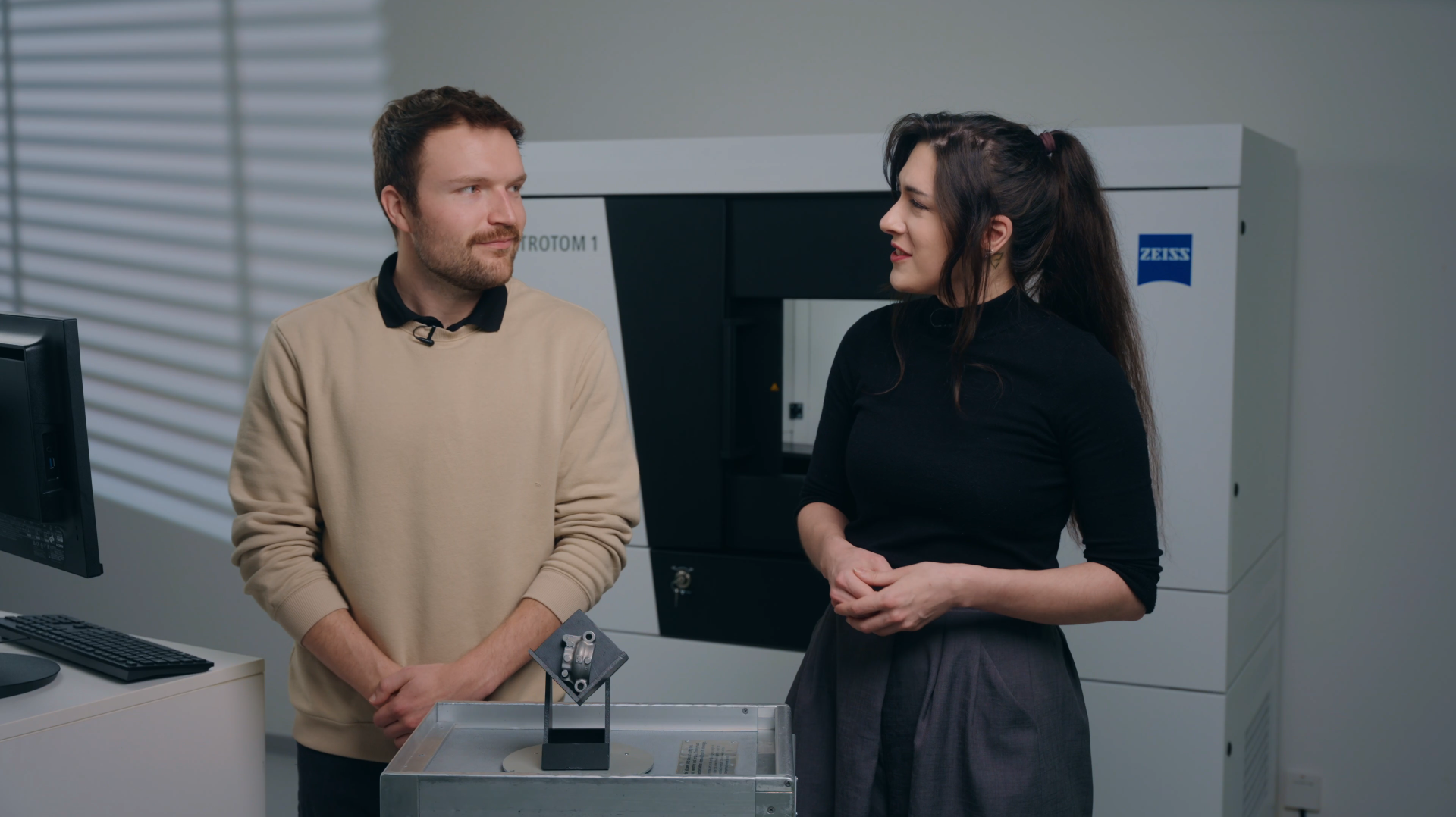
METROTOM 1: How to inspect the inside of electronic connector housings
Did you know that the 3D scanner METROTOM 1 is ideal for the overall inspection of electronic connectors housings? Let Alex show you how a simple 3D scan – powered by CT technology – can provide you with valuable data to determine the external and internal part quality.
Do you have any question on our 3D scanners? Contact us via support@HandsOnMetrology.com
Hol dir die Software, starte
dein Projekt.
Software
ZEISS REVERSE ENGINEERING
ZEISS REVERSE ENGINEERING: Software user interface
In this video, Josh provides a quick overview of the ZEISS REVERSE ENGINEERING software user interface and shows you how to set up and start using the software. He covers the basics, including the software settings, the workspaces and some additional functionalities. Watch it and get started!
All functions shown are available in the current software version.
Got any questions on the ZEISS software? Contact us via support@HandsOnMetrology.com
ZEISS REVERSE ENGINEERING: Most common functions
Discover the most common functions of ZEISS REVERSE ENGINEERING. In first place: the „extract surfaces from parts“ function, which leads directly to the „extract solid body“ function – two powerful tools, especially for geometry-based parts. Second place: the creation of symmetric parts. Third place: the creation of freeform surfaces. And last but not least: the analysis function of your parts. Let Josh show you what’s what.
All functions shown are available in the current software version.
Got any questions on the ZEISS software? Contact us via support@HandsOnMetrology.com
ZEISS REVERSE ENGINEERING: Importing data
Take it from Josh: Importing data into ZEISS REVERSE ENGINEERING is just as easy as importing it into ZEISS INSPECT. If ou’re already using ZEISS INSPECT, simply export into ZEISS REVERSE ENGINEERING. Alternatively, you can drag and drop files from your file explorer or use the import option as the top of ZEISS REVERSE ENGINEERING. Want to know which file types are supported? Simply take a look at the user guide.
All functions shown are available in the current software version.
Got any questions on the ZEISS software? Contact us via support@HandsOnMetrology.com
ZEISS REVERSE ENGINEERING: Edit and align meshes
Let Josh show you how to align and edit your mesh in ZEISS REVERSE ENGINEERING. Step 1: Align your mesh with the „best fit via three planes“ function to review your part in an intuitive manner. Step 2: Edit your mesh by closing small holes with the „fill holes in mesh automatically“ function. Now you have a fully closed and aligned mesh without any unwanted data – and you’re ready to start the reverse engineering process.
All functions shown are available in the current software version.
Got any questions on the ZEISS software? Contact us via support@HandsOnMetrology.com
ZEISS REVERSE ENGINEERING: Tips and tricks
In this video, Josh lets you in on some handy tips and tricks to help you get started even faster with ZEISS REVERSE ENGINEERING. Learn how to bookmark your favorite functions. Discover how the transparency tool can help you get a better look at specific elements. Learn about how the snapshot tool makes it easy for you to create images for reports. Start using the „fit to screen“ icon to get a better view of your part. And minimize clicks by looking at the shortcut list in the user guide.
All functions shown are available in the current software version.
Got any questions on the ZEISS software? Contact us via support@HandsOnMetrology.com
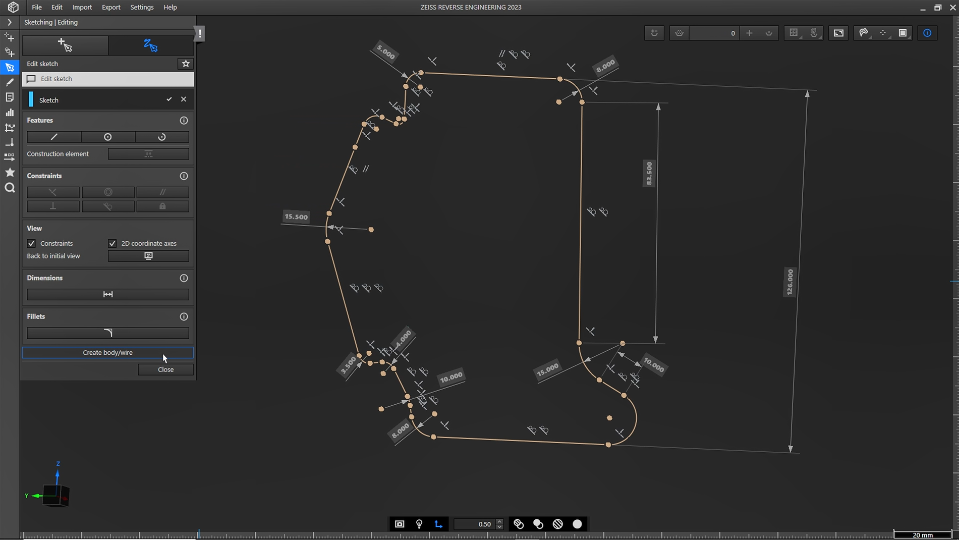
New Sketching function in ZEISS REVERSE ENGINEERING
Looking for an easy way to get more control over your reverse engineered models? With the new sketching function in ZEISS REVERSE ENGINEERING, creating CAD models is easier than ever. Your benefit: fully dimensioned and constrained CAD from scan data.
Do you have any questions about ZEISS REVERSE ENGINEERING? Contact us via support@HandsOnMetrology.com
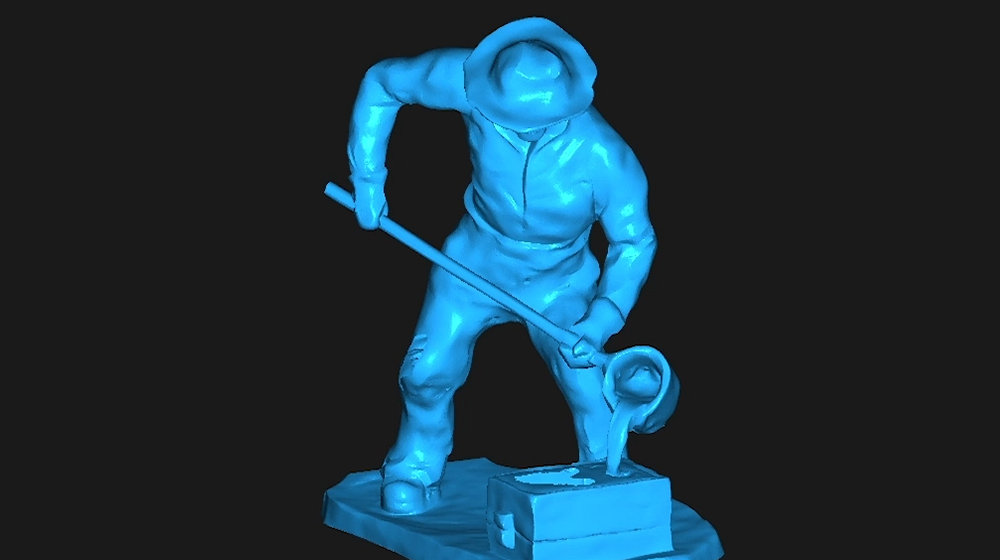
ZEISS REVERSE ENGINEERING: How to create a CAD file out of manually modelled parts
Looking for an easy way to create a CAD out of your individually modelled part? Let Matt show you how! With the help of the ATOS Q and the ZEISS REVERSE ENGINEERING software the part gets digitized and undergoes step by step virtual modeling. Helpful features support the process to enable fast and intuitive work.
All functions shown are available in the current software version.
Got any questions on 3D scanning? Contact us via support@HandsOnMetrology.com
ZEISS REVERSE ENGINEERING: How to transform your 3D scans into CAD models
Meet Josh and let him show you how to transform your 3D scans into CAD models using the software ZEISS REVERSE ENGINEERING. Wether you want to reverse engineer a geometrical part, a freeform shaped part or an organic shaped part – Josh gives you a quick introduction to each task, from scanning to obtaining a CAD model.
All functions shown are available in the current software version.
Got any questions on 3D scanning? Contact us via support@HandsOnMetrology.com
ZEISS INSPECT
ZEISS INSPECT: Optical 3D User Interface
Find out how to perform accurate 3D data evaluation in ZEISS INSPECT. Whether you are facing simple or more complex inspection tasks, the software has it all: mesh editing functions, CAD import, GD&T inspections, trend analysis and digital assembly.
Do you have any questions about ZEISS INSPECT?
Contact us via email: support@HandsOnMetrology.com
ZEISS INSPECT: Data import
Starting your 3D inspection is easy with ZEISS INSPECT. Learn which formats are supported in our software and how easy it is for you to import your 3D data.
Do you have any questions about ZEISS INSPECT?
Contact us via email: support@HandsOnMetrology.com
ZEISS INSPECT: Performing single inspection
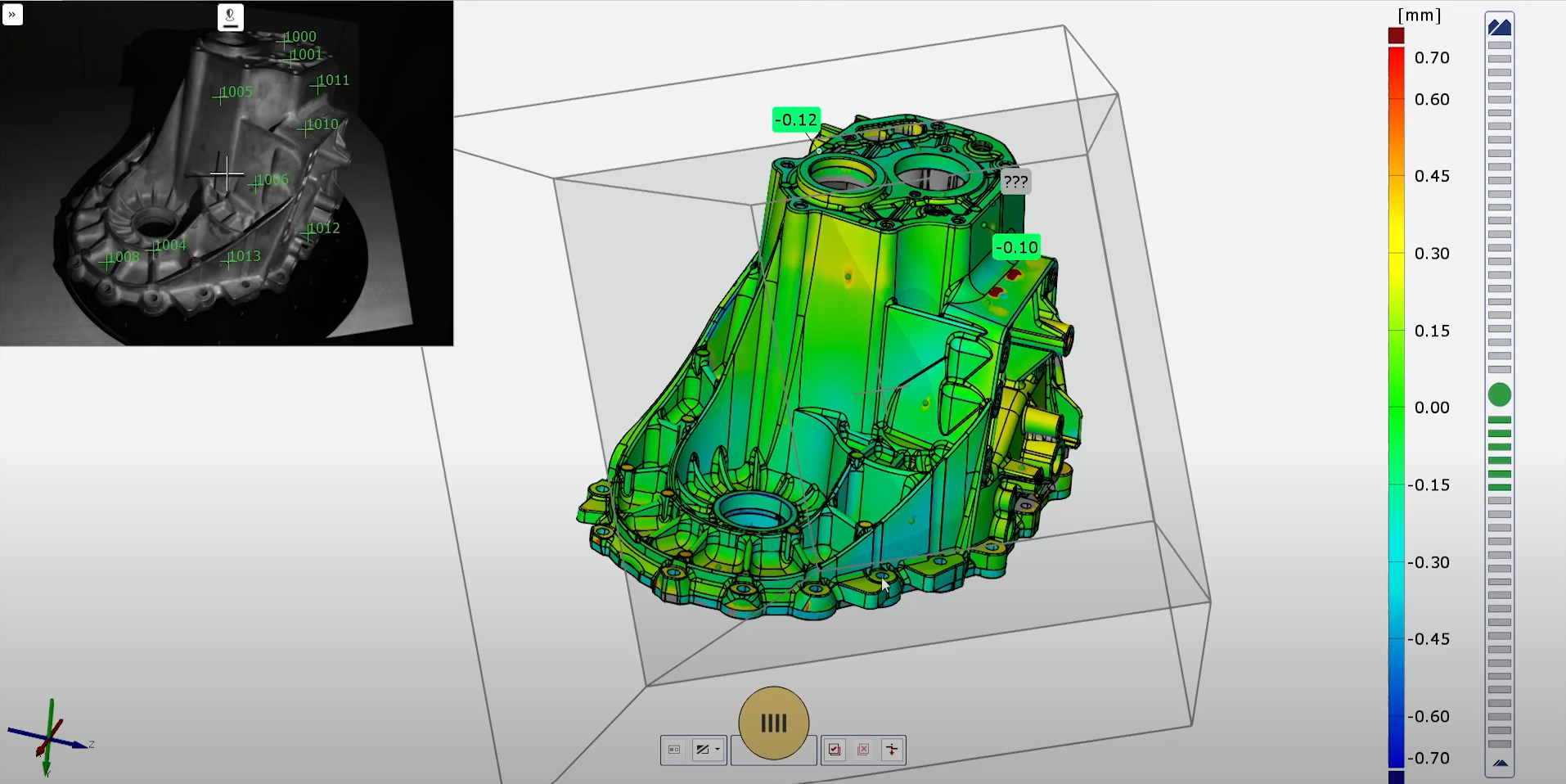
Learn how to compare your 3D data to the CAD in ZEISS INSPECT. The software solution offers you a wide range of inspection possibilities, like the color plot, deviation labels for discrete deviation labels or the clipping functionalities for small or hard to reach areas.
Do you have any questions about ZEISS INSPECT?
Contact us via email: support@HandsOnMetrology.com
ZEISS INSPECT: Performing GD&T inspections
Learn how to compare your 3D data to the CAD in ZEISS INSPECT. The software solution offers you a wide range of inspection possibilities, like the color plot, deviation labels for discrete deviation labels or the clipping functionalities for small or hard to reach areas.
Do you have any questions about ZEISS INSPECT?
Contact us via email: support@HandsOnMetrology.com
ZEISS INSPECT: Reporting
Need tips on how to create, edit and present your 3D inspection reports? The ZEISS INSPECT report workspace got you covered. Learn here how to use the workspace to receive comprehensive and customizable reports pages.
Do you have any questions about ZEISS INSPECT?
Contact us via email: support@HandsOnMetrology.com
How to perform CAD surfacing in ZEISS INSPECT
No CAD available for projects like 3D printing? The new surfacing function in ZEISS INSPECT got you covered. With a simple mouse click you receive a customizable CAD based on our 3D scan data. Let Luca show you how to simplify the creation of CAD with the latest release ouf our software solution.
Do you have any questions about ZEISS INSPECT? Contact us via support@HandsOnMetrology.com
How to deliver first class report presentations
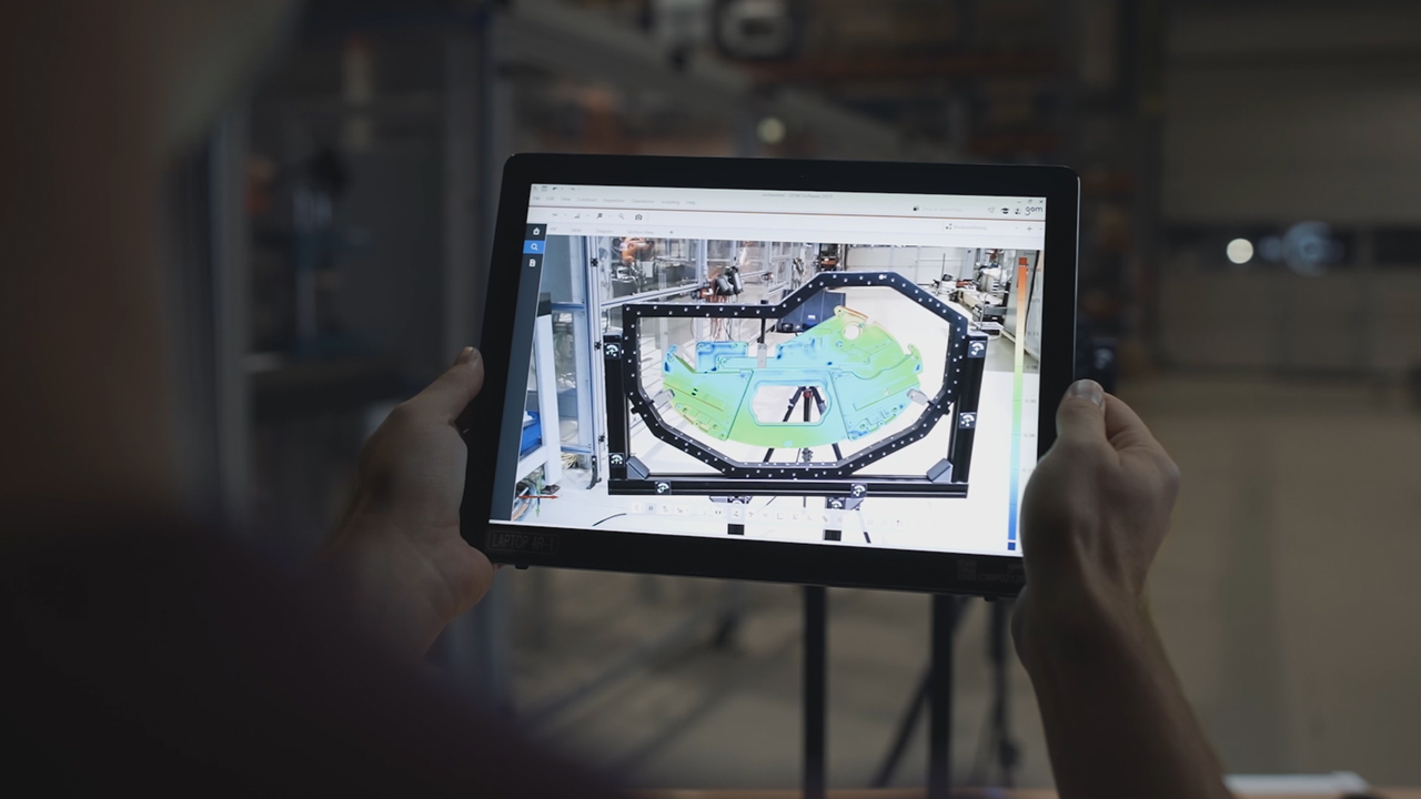
Let Norman show you how to deliver impressive presentations with ZEISS INSPECT. Simply export your measurements to a PDF? It’s an option, but a static one. You can do better! Simply open ZEISS INSPECT in the meeting room, hit the F5 key for the presentation mode – and get the option to zoom in or rotate the part and adjust the display. You can even show your mesaurement results on the object – with the help of a tablet and AR. Now, that’s impressive.
All functions shown are available in the current software version.
Got any questions on 3D scanning? Contact us via support@HandsOnMetrology.com
Möchtest du noch mehr wissen?
Nehmen Sie Kontakt mit Ihrem lokalen #HandsOnMetrology-Partner auf.
