


Weld inspection: testing methods and automation
A weld inspection is a key element of quality assurance in welding technology. Various test methods can be used to identify weld defects such as cracks or lack of fusion in welded joints. The new weld check package in the ZEISS INSPECT software allows for automated and standardized non-destructive testing of welds. Together with the hand-held ZEISS T-SCAN hawk 2, selected scan data can be evaluated with maximum convenience.
What is a weld inspection?
A weld inspection is used to check the quality of a component’s welds. This quality control is particularly important to ensure that the welds are strong and can withstand the stresses of everyday use. A weld inspection can directly identify and evaluate defects or discontinuities in the welded joints, such as cracks, porosity, blowholes, foreign inclusions, incomplete penetration or deviations in shape and dimensions.
How do you test welds?
There are various weld inspection methods which can be roughly divided into non-destructive and destructive tests. To perform a non-destructive test (NDT) on the surface of a weld, the following methods are used: visual inspection, dye penetrant testing, eddy current testing or magnetic particle testing. Defects inside a welded joint can be identified non-destructively by way of X-ray or ultrasonic testing.
When destructive testing methods are used for welds, the part is damaged, or even destroyed, to assess weld quality and detect weld defects. The welded joints are subjected to various tests, for example the tensile test, hardness test, bend test or corrosion test. This makes it possible to determine properties such as hardness, durability, or tensile strength. Destructive testing methods are often used for test objects and initial samples, while non-destructive testing of welds is used in serial production.

Non-destructive testing methods for welding
Visual inspection
When visually inspecting welds, the weld is checked for any flaws that are visible to the naked eye using a few aids such as a magnifying glass, an endoscope, or a camera. This makes it possible to directly detect any obvious defects or deviations in shape and size.
Laser triangulation
With this method, laser points or beams and cameras with sensors are used to record the surface geometry of the weld. By evaluating the reflected light and the angle it hits the sensors, geometric defects such as warping or distortions in the weld can be identified. This technology makes it possible to assess the weld quality quickly and precisely.
Interferometry
This high-precision method uses light wave interference to detect the slightest irregularities and changes in the surface topography of the weld. By superimposing split and recombined light waves, an interference pattern is created that provides precise information about any surface defects. This technology is particularly suitable for safety-critical applications that require the highest quality standards.
Digital image processing
High-resolution cameras and the corresponding software can be used to develop automated testing procedures for quality control and evaluation of welds.
Magnetic particle inspection
Surface cracks can be detected by magnetizing the part and applying magnetic powder to the weld. Flaws such as lack of fusion generate small leakage fields on the surface which attract the magnetic powder.
Dye penetrant inspection
During this weld inspection, a colored test agent is applied to the weld, which settles in cracks and makes them visible.
Eddy-current testing
This weld inspection can be used to detect both surface and subsurface defects. Defects in the weld change the flow of magnetic currents, which is detected and interpreted by special testing devices.
Ultrasonic testing
Ultrasonic examinations can be used to detect discontinuities and flaws in the material. During ultrasonic testing, an ultrasonic transducer sends sound waves through the material, which are reflected at defective areas. The returning waves can be analyzed to precisely detect both surface and internal discontinuities.
X-ray testing
This method uses X-rays to illuminate the internal structure of the weld. Deviations in the material, such as pores or inclusions, absorb the X-rays differently and therefore appear as contrasts on the X-ray image.
Destructive test methods for welding
Hardness test
This weld inspection measures the resistance of the material to penetration by a solid object to evaluate the mechanical properties of the weld.
Tensile testing
This technique involves stretching the part until it breaks apart at the weld. This makes it possible to determine the load capacity and strength of the weld.
Bend test
In a bend test, the part is bent progressively until it breaks at the welded joint. This makes it possible to determine the quality and properties of the ductile deformation.
Corrosion testing
This weld inspection tests the resistance of welded joints in corrosive environments. The part can be subjected to a salt spray test, an immersion test, condensation, electrochemistry, high temperatures and pressure or similar.

Automated vs manual visual inspection of welds
Inspecting welds for defects is extremely important, as defective welds result in damaged parts or, in the worst case, the failure of entire welded structures. This can pose a high safety risk for both people and the environment. This is why many industries are obliged to carry out weld inspections. Depending on the test method and welding design, different standards apply to ensure the quality of welded joints and welding process tests.
One of the most important and usually also the first weld inspection, the visual inspection, is carried out in accordance with DIN EN ISO 13018. As the name suggests, the surface of the weld is closely examined by trained specialists. This way, any obvious deviations in the shape, dimensions and surface structure can be detected straight away. However, there are a few challenges to overcome when visually inspecting welds. According to the ISO standard, the welded joint should be sufficiently illuminated to at least 500 lux. However, the rooms in which testing takes place are not always brightly lit and welds are often located in hard-to-reach areas of the part. This means that flashlights are often used. A range of manual measuring devices are also used, such as callipers, three-scale gauges, and seam gauges. The inspector uses these tools to take numerous measurements and then compares them with the permissibility criteria of the stipulated standard for the welding process test. Many manual steps mean a high potential for error. Visual testing takes a great deal of time, especially for poorly accessible welds, and the lack of a digital test report for the visual weld inspection also makes it difficult to trace and check for defects occurring later. Automated weld inspection could be the ideal solution to this problem. But is it even possible to automate and standardize these weld inspection procedures?
Visuelle Prüfung eines Motorradrahmens: die Software im Detail
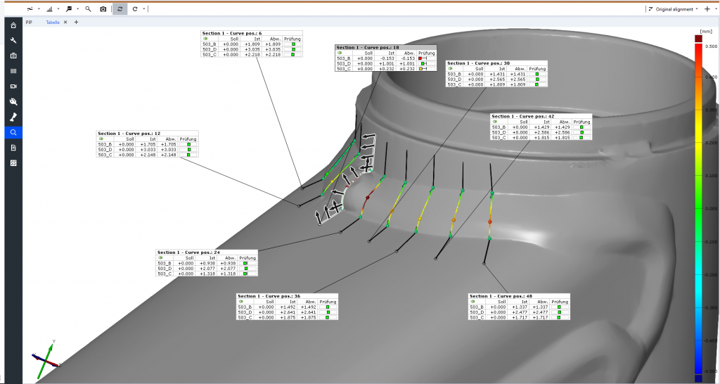
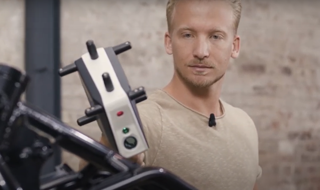
Mit der Kombination aus dem 3D-Scansystem und der Schweißnahtprüfungsfunktion in GOM Inspect Pro ist eine automatisierte Sichtprüfung an jedem beliebigen Teil möglich, unabhängig von Größe und Form. In diesem Beispiel dient ein Motorradrahmen zur Veranschaulichung. Nachdem dieser mit dem handgeführten T-SCAN Hawk vermessen wurde, werden die Scandaten in die GOM Inspect Pro Software geladen. Danach folgt die eigentliche Prüfung der Schweißnähte. In der Software wird eine einfache Kurve verwendet, um die zu prüfende Schweißnaht auszuwählen. Anschließend kann eine beliebige Anzahl von Abschnitten definiert werden, z. B. alle in einem Abstand von 10 mm. Diese Abschnitte des Motorradrahmens können nun mit der neuen Zusatzfunktion „Weld Check“ (Schweißnahtprüfung) ausgewertet werden. Alle Merkmale der DIN-Norm 5817 sind dort automatisch hinterlegt und werden nicht nur per Mausklick geprüft, sondern auch direkt in die entsprechenden Bewertungskategorien B, C oder D eingeordnet. Grün bedeutet erfüllt, orange zeigt an, dass sie gerade noch innerhalb der Toleranz liegt und rot bedeutet, dass sie die Kriterien nicht erfüllt.
In unserem Beispiel entspricht die ausgewählte Schweißnaht nur in einem Abschnitt nicht den Vorgaben für die Schweißnahtverstärkung. Bereits bei der Prüfung der einzelnen Merkmale können separate Berichte erstellt werden. Selbstverständlich ist auch eine Gesamtprotokollierung aller Merkmale des VTs möglich. Dies ermöglicht eine digitale Dokumentation aller durchgeführten Sichtprüfungen. Ist eine Referenz in der Software hinterlegt, kann auch die Lage und Vollständigkeit der Schweißnähte überprüft werden. Diese Referenz kann ein CAD-Modell oder ein 3D-Scan sein. So kann bei einer Kleinserie von Motorradrahmen der Musterscan als Vorlage gespeichert werden und als Maßstab für die Serienprüfung dienen.
Beginnen Sie jetzt mit der automatischen Prüfung von Schweißnähten
Wenn Sie daran interessiert sind, jetzt mit der automatischen Schweißnahtprüfung zu beginnen oder mehr über 3D Scansysteme erfahren möchten, wenden Sie sich einfach an support@handsonmetrology.com. Sie können hier auch eine Demo für das Weld Check Package anfordern, das in der GOM Inspect Pro Version verfügbar ist.