De el escaneo 3D al modelo CAD con ZEISS REVERSE ENGINEERING
¿Busca una solución de software que le facilite la ingeniería inversa? ZEISS REVERSE ENGINEERING está preparado para llevar sus datos al siguiente nivel. Escanee sus piezas en ZEISS INSPECT o cualquier otro software e importe sus formatos STL, PLY y ASCII a ZEISS REVERSE ENGINEERING. Sólo son necesarios unos pocos pasos bien guiados para conseguir un modelo CAD de alta precisión que puede exportarse a formatos CAD estándar como IGES, STEP o SAT. Así que, sea cual sea su tarea de ingeniería inversa: llegue a ella de forma rápida y sencilla.
Un potente software de ingeniería inversa
Un flujo de trabajo guiado
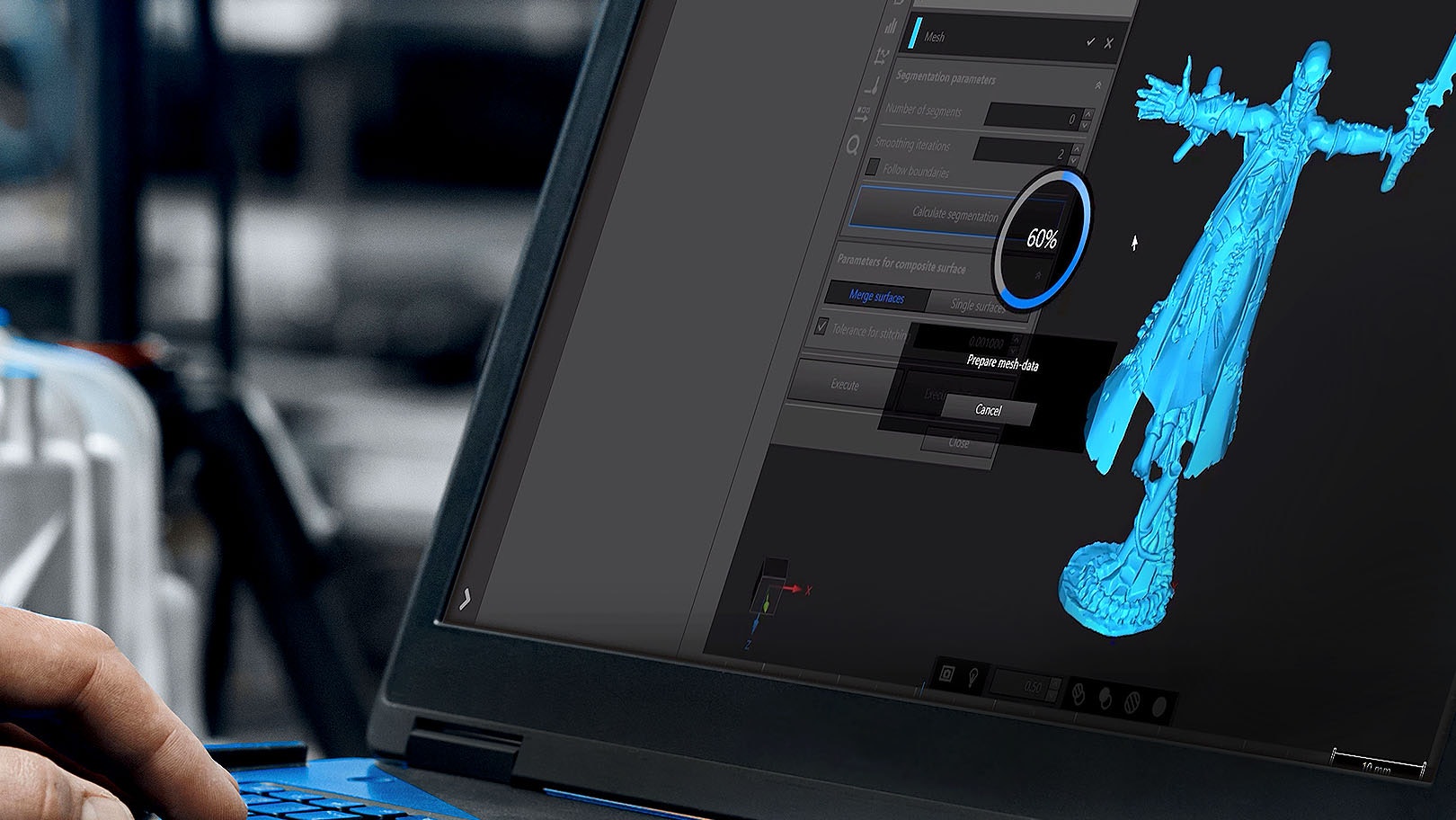
ZEISS REVERSE ENGINEERING facilita la generación de un modelo CAD a partir de datos de escaneado, como mallas poligonales o nubes de puntos, y le guía paso a paso por el flujo de trabajo.
Alta precisión
ZEISS REVERSE ENGINEERING ofrece superficies CAD corregidas con la máxima precisión. Esto es esencial si desea producir piezas de plástico con requisitos de precisión muy elevados.
Funciones efectivas
Prepare sus datos con funciones como el relleno de agujeros y el aplanamiento, y continúe con funciones como el mejor ajuste dinámico o la extrusión.
Consiga su modelo CAD, sin importar la forma
Scan to CAD for geometrical part
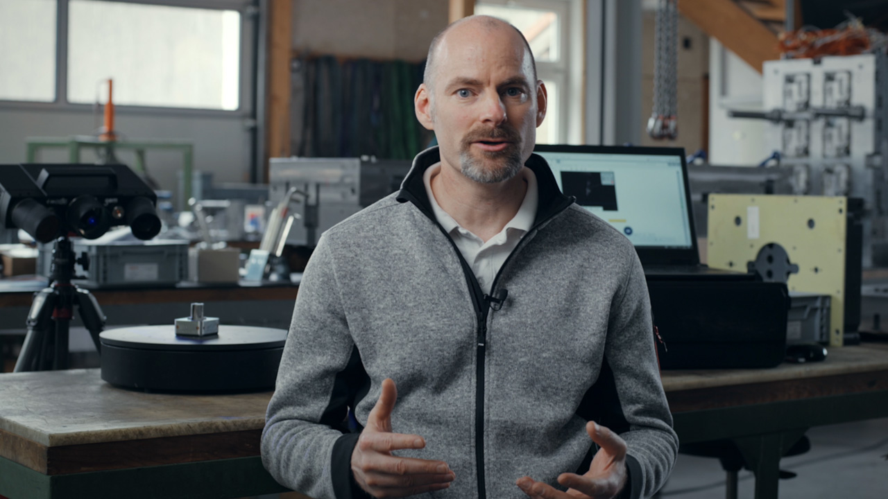
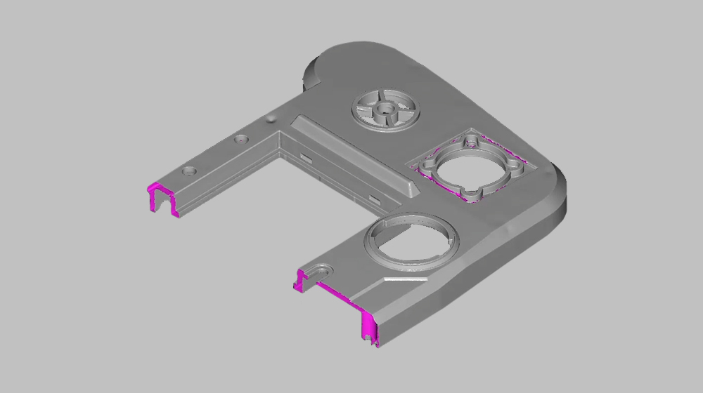
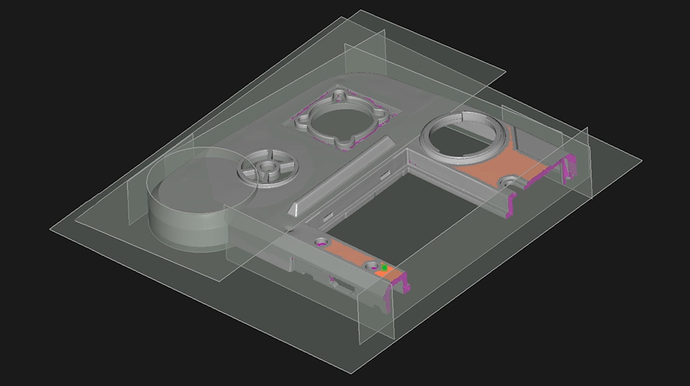
Follow Josh’s instructions to scanning a geometrical part and transforming it into a CAD model using ZEISS REVERSE ENGINEERING and the GOM Scan 1. First, he scans a symmetrical part and cuts it in half. Then, he creates basic elements of the part with planes from the mesh. Next, he creates a body from these elements and add details. Finally, he mirrors the part – and has a perfect CAD model of the part.
Piezas geométricas
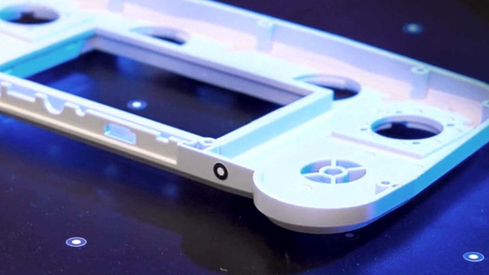
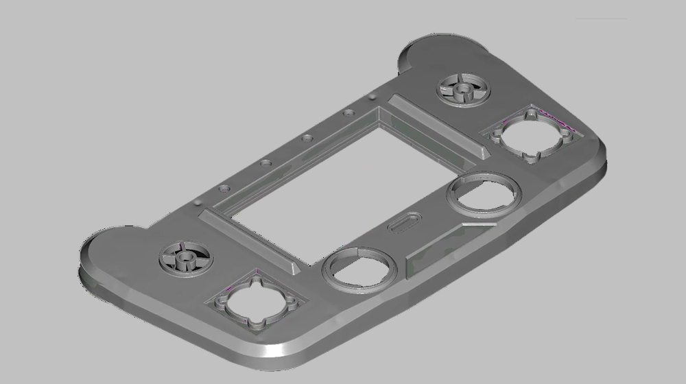
¿Ingeniería inversa para formas geométricas? Exporte su malla a ZEISS REVERSE ENGINEERING y comience a crear, combinar, extraer y ajustar. Mientras lo hace, tiene el control de todo el proceso y genera exactamente el resultado que necesita.
Superficies libres
ZEISS REVERSE ENGINEERING le ofrece varias funcionalidades para conseguir la máxima precisión en superficies de forma libre. Para convertir su malla, utilice, por ejemplo, «Aproximación de superficies a puntos». Después, el software le guía paso a paso hasta crear su molde.
Scan to CAD for freeform part
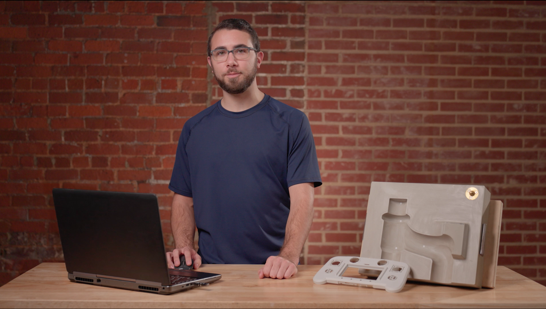
Discover how Josh uses the software ZEISS REVERSE ENGINEERING to create a mold for a freeform shaped part. First, he creates a freeform surface of an already scanned part. Then, he creates a solid cube around the part. Finally, he subtracts the freeform surface from the cube to create the final mold.
Scan to CAD for organic shaped part
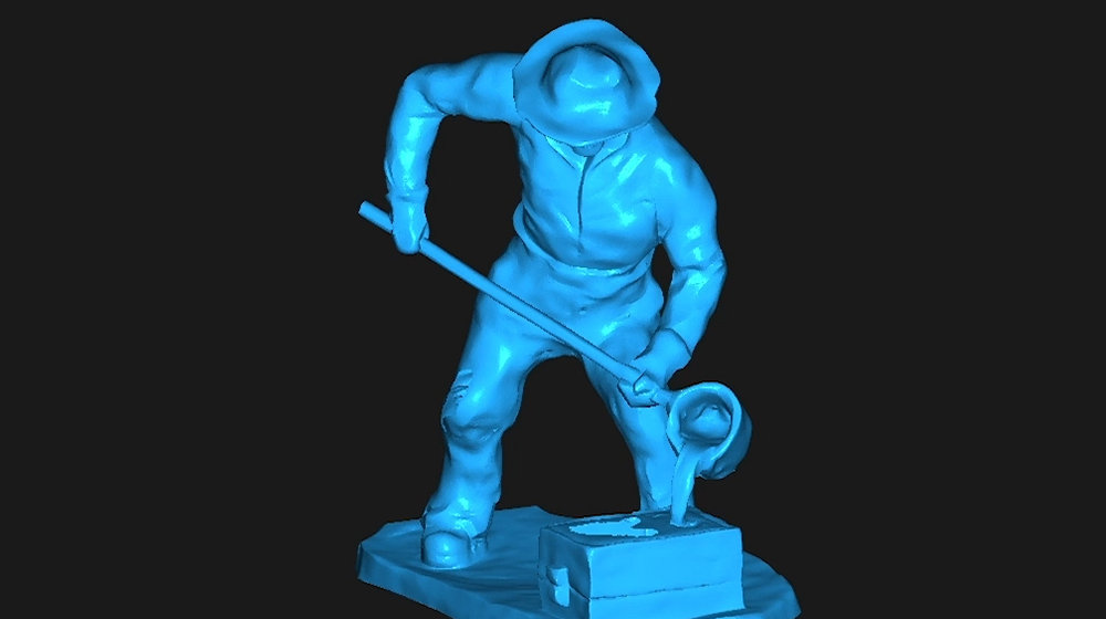
Watch Josh as he turns the scan of a highly detailed, organic shaped miniature figurine into a CAD model using the software ZEISS REVERSE ENGINEERING. First, he cleans up the mesh, closes holes and removes unwanted features. Then he simply exports the mesh to ZEISS REVERSE ENGINEERING. The result: a perfect CAD model, that follows the natural shape of the part.
Formas orgánicas
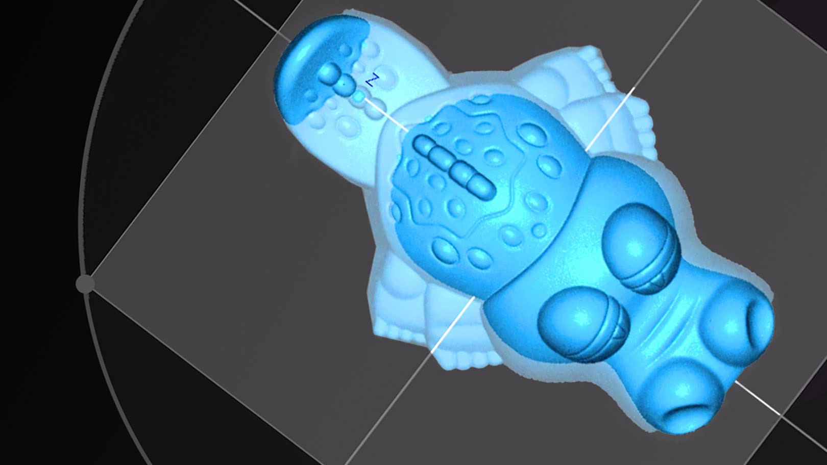
Sie quiere crear un modelo CAD para una pieza con forma orgánica o si quieres seguir haciendo ingeniería inversa, diseñando y modelando con un CAD, sólo tendrá que hacer unos pocos clics para conseguirlo. Eche un vistazo al vídeo.
Su camino fácil hacia un modelo CAD de alta precisión
ZEISS REVERSE ENGINEERING
Kostenfreie 14-tägige Testphase.
Cómo transformar sus escaneos 3D en modelos CAD
¿Tiene más preguntas sobre la ingeniería inversa de ZEISS REVERSE ENGINEERING?
No dude en ponerse en contacto con nosotros. Estaremos encantados de ayudarle.
Más información
i
Please select the topic you seek more information aboutNew Sketching function in ZEISS REVERSE ENGINEERING
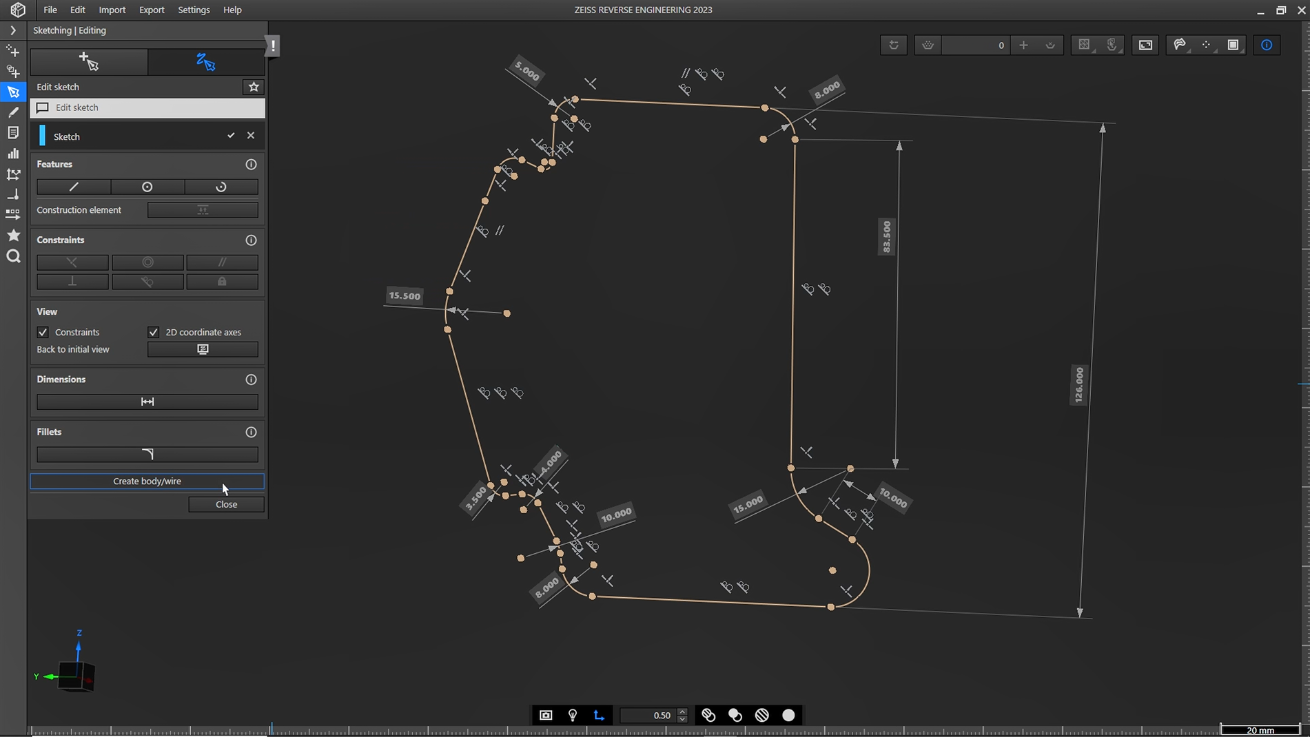
Looking for an easy way to get more control over your reverse engineered models? With the new sketching function in ZEISS REVERSE ENGINEERING, creating CAD models is easier than ever. Your benefit: fully dimensioned and constrained CAD from scan data.
Do you have any questions about ZEISS REVERSE ENGINEERING? Contact us via support@HandsOnMetrology.com
ZEISS REVERSE ENGINEERING: How to create a CAD file out of manually modelled parts
Looking for an easy way to create a CAD out of your individually modelled part? Let Matt show you how! With the help of the ATOS Q and the ZEISS REVERSE ENGINEERING software the part gets digitized and undergoes step by step virtual modeling. Helpful features support the process to enable fast and intuitive work.
All functions shown are available in the current software version.
Got any questions on 3D scanning? Contact us via support@HandsOnMetrology.com
ZEISS REVERSE ENGINEERING: Importing data
Take it from Josh: Importing data into ZEISS REVERSE ENGINEERING is just as easy as importing it into ZEISS INSPECT. If ou’re already using ZEISS INSPECT, simply export into ZEISS REVERSE ENGINEERING. Alternatively, you can drag and drop files from your file explorer or use the import option as the top of ZEISS REVERSE ENGINEERING. Want to know which file types are supported? Simply take a look at the user guide.
All functions shown are available in the current software version.
Got any questions on the ZEISS software? Contact us via support@HandsOnMetrology.com
ZEISS REVERSE ENGINEERING: Edit and align meshes
Let Josh show you how to align and edit your mesh in ZEISS REVERSE ENGINEERING. Step 1: Align your mesh with the «best fit via three planes» function to review your part in an intuitive manner. Step 2: Edit your mesh by closing small holes with the «fill holes in mesh automatically» function. Now you have a fully closed and aligned mesh without any unwanted data – and you’re ready to start the reverse engineering process.
All functions shown are available in the current software version.
Got any questions on the ZEISS software? Contact us via support@HandsOnMetrology.com
ZEISS REVERSE ENGINEERING: Tips and tricks
In this video, Josh lets you in on some handy tips and tricks to help you get started even faster with ZEISS REVERSE ENGINEERING. Learn how to bookmark your favorite functions. Discover how the transparency tool can help you get a better look at specific elements. Learn about how the snapshot tool makes it easy for you to create images for reports. Start using the «fit to screen» icon to get a better view of your part. And minimize clicks by looking at the shortcut list in the user guide.
All functions shown are available in the current software version.
Got any questions on the ZEISS software? Contact us via support@HandsOnMetrology.com
ZEISS REVERSE ENGINEERING: Software user interface
In this video, Josh provides a quick overview of the ZEISS REVERSE ENGINEERING software user interface and shows you how to set up and start using the software. He covers the basics, including the software settings, the workspaces and some additional functionalities. Watch it and get started!
All functions shown are available in the current software version.
Got any questions on the ZEISS software? Contact us via support@HandsOnMetrology.com
ZEISS REVERSE ENGINEERING: Most common functions
Discover the most common functions of ZEISS REVERSE ENGINEERING. In first place: the «extract surfaces from parts» function, which leads directly to the «extract solid body» function – two powerful tools, especially for geometry-based parts. Second place: the creation of symmetric parts. Third place: the creation of freeform surfaces. And last but not least: the analysis function of your parts. Let Josh show you what’s what.
All functions shown are available in the current software version.
Got any questions on the ZEISS software? Contact us via support@HandsOnMetrology.com
ZEISS REVERSE ENGINEERING: How to transform your 3D scans into CAD models
Meet Josh and let him show you how to transform your 3D scans into CAD models using the software ZEISS REVERSE ENGINEERING. Wether you want to reverse engineer a geometrical part, a freeform shaped part or an organic shaped part – Josh gives you a quick introduction to each task, from scanning to obtaining a CAD model.
All functions shown are available in the current software version.
Got any questions on 3D scanning? Contact us via support@HandsOnMetrology.com
Descubra nuestras sesiones de vídeo más recientes
Sesiones
Soluciones
Eventos digitales
Suscribirse a el boletín
- Política De Privacidad
- Aviso Legal
- ©2023. Todos Los Derechos Reservados
