How to use portable 3D scanning for the restoration of architecture
Historic architecture is often seen as an important part of our cultural heritage. Preserving it for future generations is a vital task. One way to achieve this goal is through restoration. It involves the process of returning a building to its original state by repairing or reconstructing damaged or missing parts. 3D scanning technology supports in this case with the collection of data necessary for the rework of hundreds years worth of history.
Editorial
The goal – restoration of 591-years-old history
Our most recent project took us to the oldest district of the city Braunschweig in Germany, called Magniviertel. Here the restoration work on a half-timbered house has been going on for the last years. With it also comes the preservation of a wooden beam which is an integral part of the building and decorates it with the inscription MCCCCXXXII. Thus, this beam makes the half-timbered house from 1432 one of the oldest dated ones. The complete and realistic preservation is a matter of great concern to the owner Christoph Borek as well as to the graduate restorer Julia Köhler and the building historian Elmar Arnhold. It helps to keep history alive.
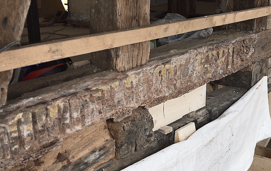
Fig. 1: Building before the restoration
Fig. 2: Wooden beam with the inscription MCCCCXXXII
A scanning approach following the motto “joint forces”
This project however requires a thorough understanding of the building’s original design, materials and construction methods along with 3D scanning technology for the necessary digitization. To join forces, we formed a team of ZEISS hard and software, years of expertise in 3D scanning at a3Ds as well as knowledge on the building, delivered by the restoration team.
For the rework of the building, a digital copy of the beam was needed. Therefore, we chose the portable, hand-held 3D scanning solution ZEISS T-SCAN hawk 2. It collects data of scanned objects and turns them into a digital twin in the inspection software. For further steps, the current condition of the wooden beam can be determined using the collected 3D data.
The generated scan is supposed to represent the positive and map the wear and possible defects. Later on in the process, the corresponding negative can be created using the digitization. With this approach we are able to restore the original shape of the beam before wear.
Choosing the right solution: portable 3D scanning
In the case of historic architecture, 3D scanning allows for a precise and accurate representation of the building’s original design. This technology can capture intricate details and measurements that might be difficult to record using traditional methods. With 3D scanning, restorers can create a detailed model of the building that can be studied and analyzed from every angle, giving a better understanding of its original form and construction.
One of the main benefits of 3D scanning for restoration is that it allows restorers to identify and analyze any damage or deterioration of the structure. By scanning the building, areas of damage or wear can be indentified. Additionally, 3D scanning can help restorers spot any missing or damaged parts of the building. This information can be used to create accurate replicas of missing elements, helping to restore the building to its original form. Another benefit of 3D scanning is that it can aid in the planning and execution of the restoration process. With a detailed digital model of the building, creating a plan for the restoration, that takes into account the original design and construction methods, is possible. This can help ensure that the restoration is faithful to the building’s original form, materials, and style.
Now that we have clarified the benefits of using optical 3D metrology, let’s have a closer look at the 3D scanning process on site.
1 Preparations
Preparations were easy and fast. First we had to make sure that collected data was referenced to each other and thus result in a complete 3D model. For this preparation step we applied reference points to the relevant component. This is done without negatively affecting the quality of the beam. The reference points also adhere to wood without any problems. Afterwards all that was left to do was to connect the laser scanner with the laptop via a power delivery hub.
This done, we were ready to go!
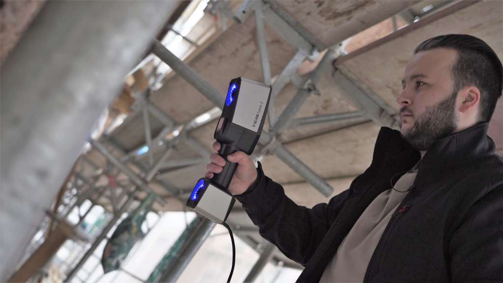
2 On-site with 3D scanner ZEISS T-SCAN hawk 2
The conditions on-site were not ideal, but we had an optimal system on hand: the ZEISS T-SCAN hawk 2. The hand-held system’s design makes it suitable for the flexible use at the inspection site. Tripod-guided systems, would only be suitable to a limited extent due to the narrow inspection space and the construction site environment. The harsh environmental conditions are no challenge for the ZEISS T-SCAN hawk 2. The scanner even compensates for movements during measurements. The surface of the beam and the inscription thus were quickly and accurately measured at a height of 5 meters. This is made possible by the scanners’ multi and single laser lines. Want to know a secret? Even without a power supply on-site, a measurement was performed using the battery-supported approach.
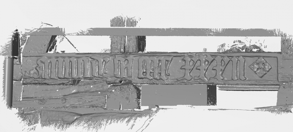
It was just a matter of a few minutes that we started seeing the first data in the inspection software of the ZEISS Quality Suite. We quickly received an accurate mesh of the wooden part. Even detailed STL data was generated on the spot. This shows the actual condition as well as the wear of the component. The data is essential for the 3D milling contour modulation by a wood construction technician to complement the wear.
Fig. 3: 3D mesh of wooden beam in the inspection software
4 Finishing touches
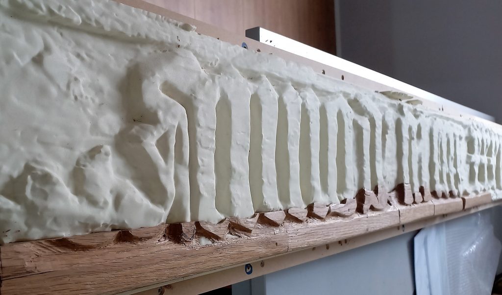
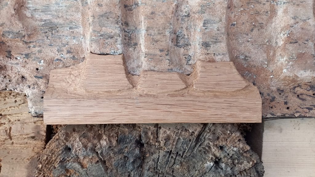
For a perfect fit to the original, the beam was milled in plastic first. The wood additions got adjusted to the missing part on the plastic beam (with e.g. carving iron). These additions were then glued and doweled to the original wooden beam.
Fig. 4: Wooden additions on milled plastic beam
Fig. 5: Wooden additions on the original beam
5 Experience first hand
You are interested in the scanning project and the historical background? Get more details in our latest Vlog:
Get to know ZEISS T-SCAN hawk 2
You want exclusive insights into the work with the new ZEISS T-SCAN hawk 2?
Feel free to book a free demo and try for your individual inspection tasks.