3D scanning of turbines was performed successfully in several hydroelectric
power plants in order to assess the condition and the efficiency of these
turbines, to check their shape, to create copies or to prepare new ones. The 3D scanning system and TRITOP allow for high accuracy measurements even of large and complex components like water turbines. Such a detailed 3D model detects the slightest deviations from the ideal geometry of the rotor.
Editorial
Our partner TOPOMATIKA has successfully teamed with the Croatian Institute of Civil Engineering and the Croatian Electric Power Industry. Via a team effort several hydroelectric power plant turbines were digitized with a 3D optical scanning system to create various 3D “As Built” digital representations. These “As Built” data sets were utilized to deliver “As Built Vs. As Designed” inspection reports to aide in assessment of the turbines condition and efficiency. The 3D scan data was also utilized to create duplicate components and set a baseline to generate new designs. The non-contact 3D optical digitizing system facilitates the accurate and detailed scanning of both simple and complex objects. Combined with the TRITOP Digital Photogrammetry system, objects from jet propulsion to ground based power generation turbines to full scale aircraft can be rapidly and accurately scanned. The measuring systems are portable, easy to transport and allow for on-site 3D scanning (in power station, on shop floor, etc.). With a portable 3D scanning system it is no longer necessary to take the object to the measuring laboratory.
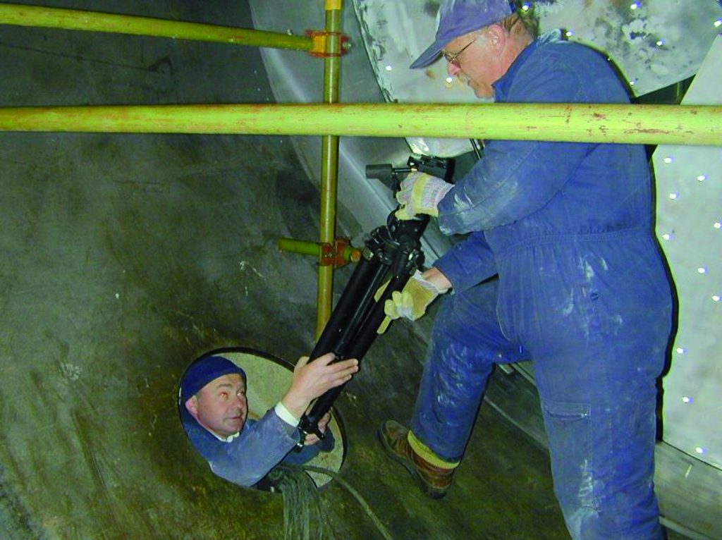
Fig. 1: The measuring systems are passed through a small opening into the turbine of a hydroelectric power plant.
The measuring session facilitated the assessment of the installed turbine rotor.
3D Scanning of the Pelton Turbine Rotor
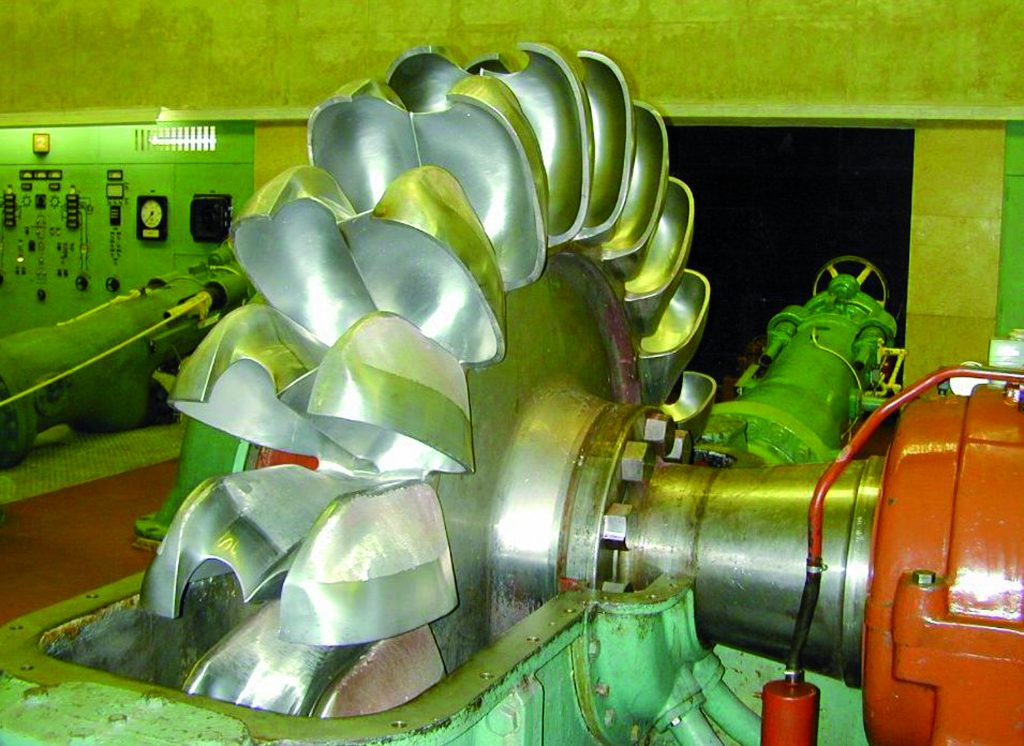
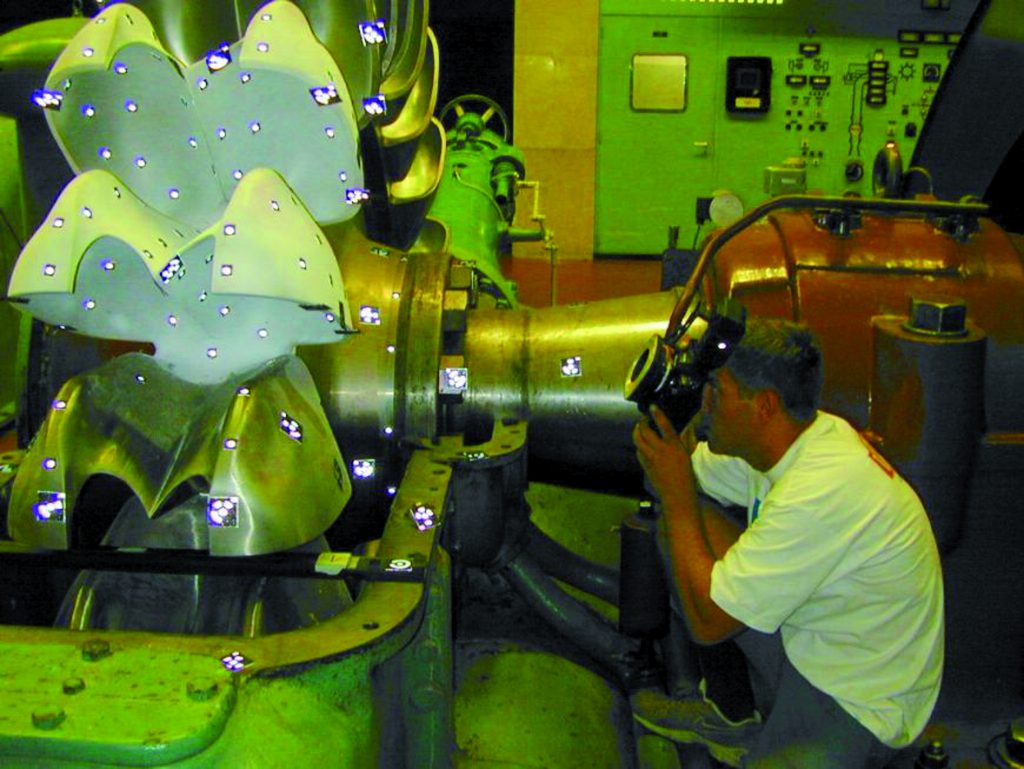
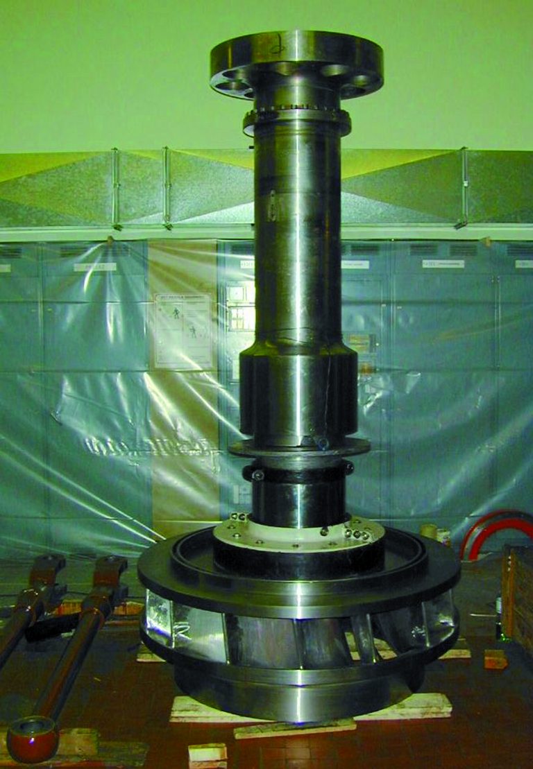
Pelton turbines are used in hydroelectric power plants with high water pressures and low amounts of water (fig. 2). As these water turbines run at great speed, the rotor’s geometry and steady rotation are key performance criteria. 3D digitizing of the rotor starts with a Digital Photogrammetry (TRITOP) session utilizing a hand held professional grade digital camera (fig. 3). The TRITOP software processes the acquired session images and automatically calculates the exact position of the reference markers that were applied to the turbine’s rotor and blades.
Fig. 2: Rotor of a Pelton turbine
Fig. 3: Photogrammetric image recording
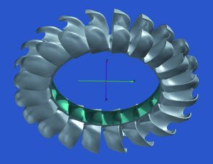
The 3D scanning system projects a dense fringe pattern on the surface of the object. These patterns are recorded by dual digital cameras, processed and result in scan data (point cloud) representative of that area of the object. During the scan process, the system also accurately defines the center of the reference markers visible in the measured area. Based on the unique orientation of these reference markers, the scan data patches are automatically and accurately merged together. Depending on the 3D scanning system, each scan takes from 1 to 7 seconds and can generate up to 4 million 3D measuring points per scan. Via this method, the shape of a blade segment can be acquired and verified quickly and accurately. This scan process was repeated until the turbine rotor blades were digitized from all sides. In the case of the Pelton turbine rotor, the various 3D scans were automatically merged together based on a global reference marker position file created via a TRITOP Digital Photogrammetry session. Fig. 4 shows the shaded 3D measuring data of the digitized rotor. The resulting data file consists of millions of 3D points describing in detail the shape of each blade. The resolution (point density) of this is approx. 0.3 mm (.010 in). If required, the 3D scanning system can be easily adjusted to deliver high resolution or an increased measuring field.
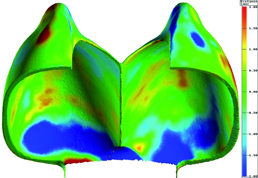
The benefit of such a detailed and accurate 3D “As Is” digitized model can detect the slightest deviations from the ideal geometry of the rotor. The data of the scanned turbine blades can be compared with the CAD model (if available), with the data of other blades, or for symmetry checks the data can be mirrored, see fig. 5. The deviations in the shape are represented in different colors corresponding to the scale on the right side in the image. Areas in which the shape of the turbine blades deviates up to 2 mm (.08 in) are clearly visible (red and dark blue regions). It is also possible to display and export the result with fewer measuring points (thinned data set) or as sectional data depending on the task to be performed and the capabilities of the downstream processing software and system (fig. 6).
Fig. 4: 3D scan result of the Pelton turbine's rotor
Fig. 5: Deviation of the shape of two blades
Fig. 6: Turbine rotor sector, displayed as thinned data set
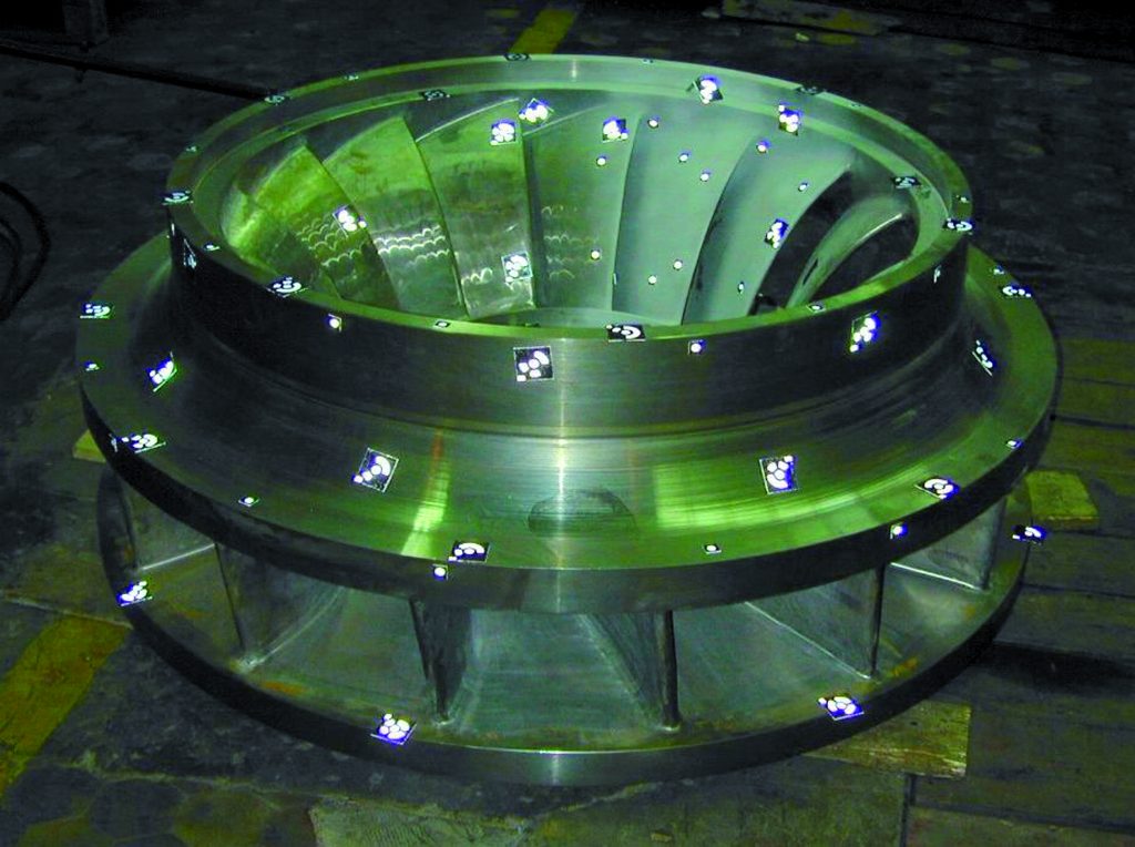
3D Scanning of a Francis Turbine Rotor
Francis turbines are widely used in hydroelectric power plants (fig. 7). They are used for medium water pressure (drop height) and medium amount of water and excel because of their high efficiency in various operating conditions. The blades of the Francis turbine are very curved and densely configured. At the end of the manufacturing process they are manually ground and polished. It is difficult to access the water inlet channels. Therefore, manufacturing of these turbines is both complicated and expensive. It is also very difficult and time-consuming to measure and inspect the shape of the blades using traditional measuring methods.
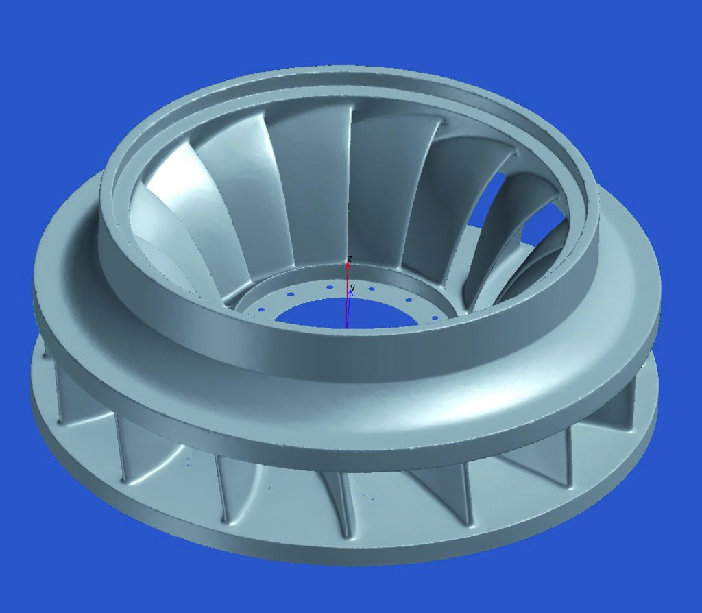
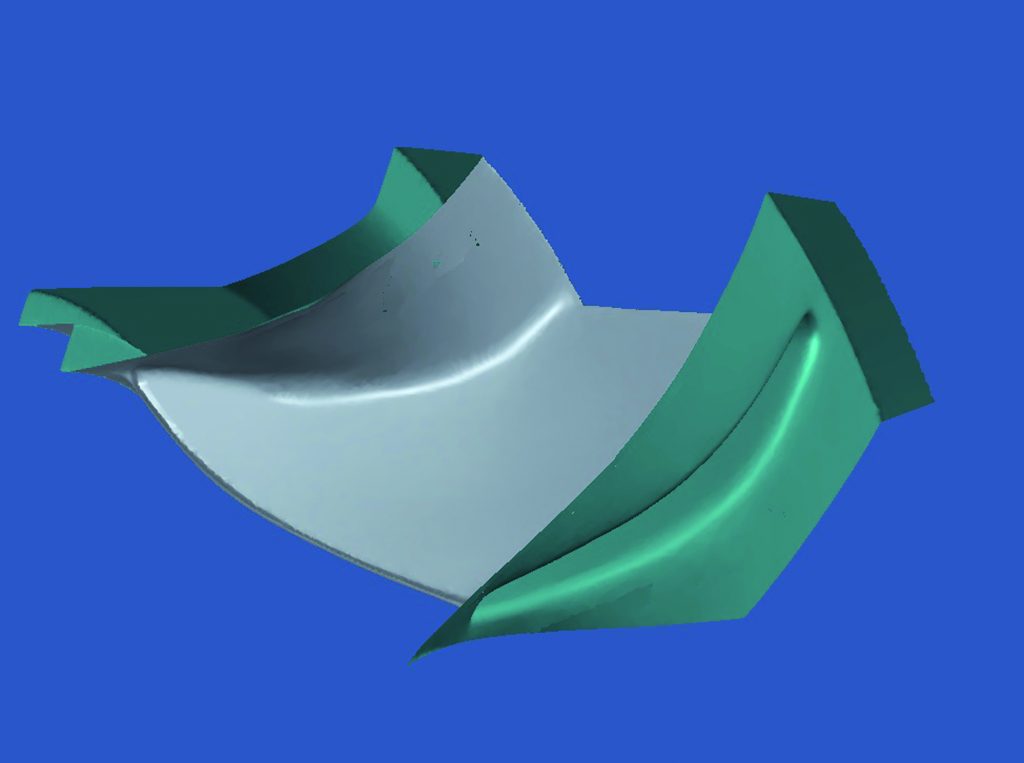
Similarly as with the Pelton turbine, the Francis turbine’s rotor 3D digitization was performed utilizing the 3D scanning and TRITOP Digital Photogrammetry combination. The result was a 3D triangular mesh consisting of millions of data points. The 3D scanning system efficiently and effectively scanned the complete surface of the blades generating an accurate 3D representation (fig. 9 & 10) despite the part complexity, which makes utilizing traditional measuring methods both cumbersome and time consuming.
Fig. 7: Turbine rotor with output shaft
Fig. 8: Preparing the rotor for 3D scanning
Fig. 9: Shaded 3D scan data of a Francis turbine rotor
Fig. 10: Display of an individual turbine blade, portion of the scanned data of the entire rotor
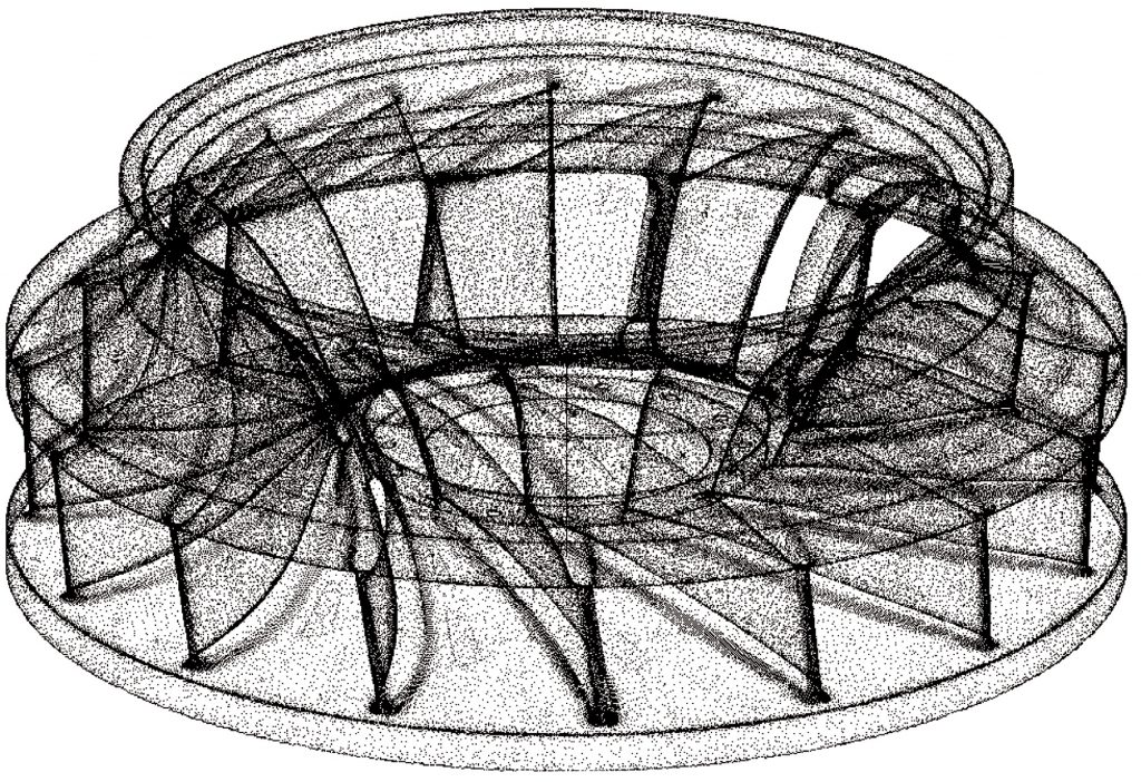
There are many processes which benefit from the full 3D rotor scan; “As Built Vs As Designed” analysis, Dimensional Inspection, “As Built” model generation for FEA and CFD analysis, manufacturing a duplicate replacement rotor directly from scan data, creating smaller or larger replicas for test purposes, and creating a CAD or digital definition for various other applications. If required, the rotor can be represented with a reduced amount of points (fig. 11) or with parallel sections (fig. 12).
Fig. 11: Reduced scan model
Fig. 12: Representation with parallel sections
Checking the Geometry of a Kaplan Pipe Turbine
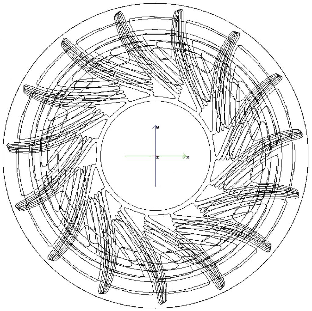
Two Kaplan pipe turbines in the Dubrava hydroelectric power plant located on the river Drava produced cyclical vibrations detrimental to their operation. These vibrations were particularly noticeable in generator A1 while generator A2 rotated much smoother. In order to understand and, if possible, correct this condition, the shape and position of the blades of both wheels were scanned and evaluated (fig.13). For this purpose it was necessary to determine the exact distance to the adjacent blades (angular position), the shape tolerance of the blades and the alignment of the blades with respect to the centerline of the turbine’s rotor.
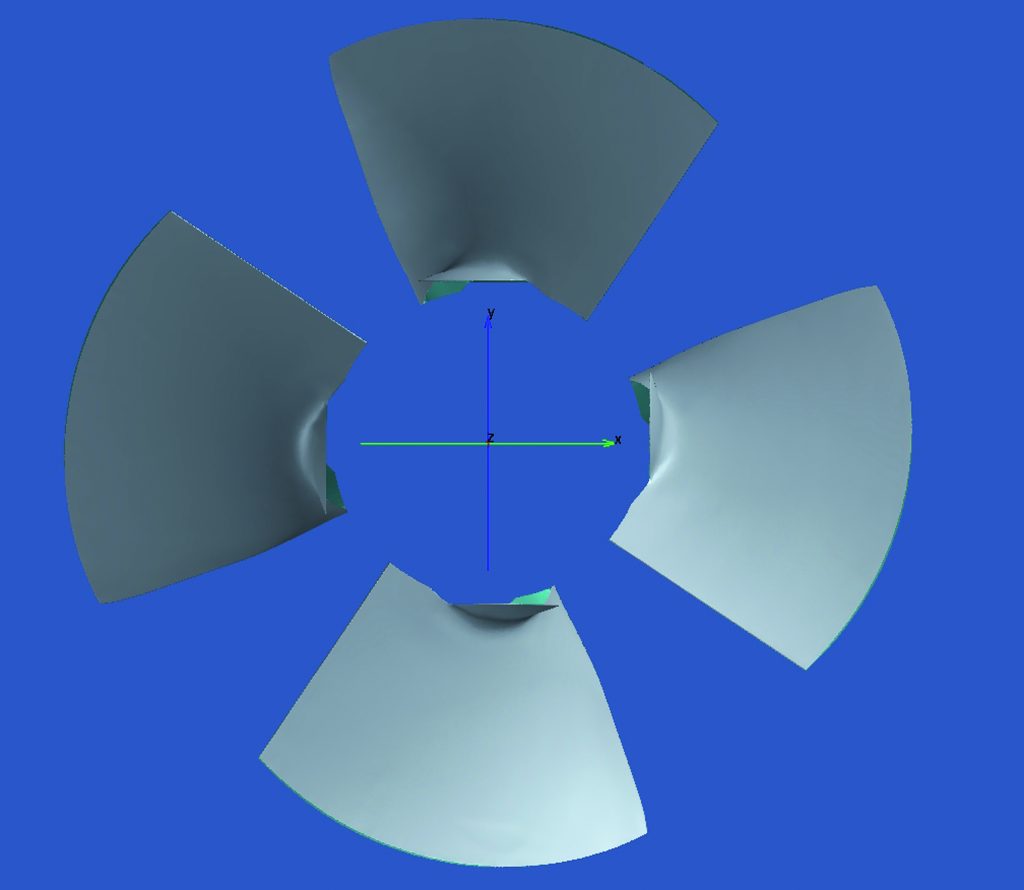
Using the 3D scanning and TRITOP Digital Photogrammetry system, detailed 3D scanning of the blades of both rotors in different positions and rotation angles was carried out. The 3D scan results (fig. 14) allow for a detailed comparison of the blade shapes. Figure 15 shows a cross section of the leading edge of the four blades of rotor A1. A considerable deviation is particularly noticeable in the section A-A at the wheel hub. Rotation of the rotor made it possible to scan all blades in the same position and to determine the irregularities in the installation of the blades on the shaft.
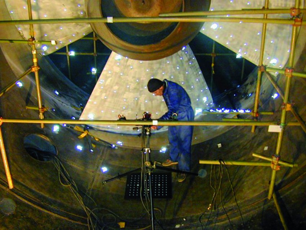
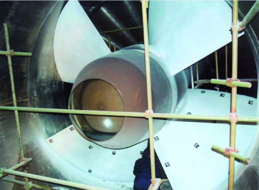
Fig. 13: Preparation of the turbine wheel (5.4 m diameter) for 3D scanning
Fig. 14: Shaded 3D scan data of the blades created utilizing the combined 3D scanning and TRITOP process
Fig. 15: Shape of the blades along the section in the area of the leading edge
Fig. 16: Surface deviation of the first and fourth blade of generator A1, caused by the differences in shape and irregularities of installation on the shaft
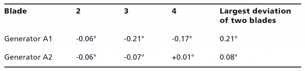
Tab. 1: blade angles of generators A1 and A2
Table 1 shows the different blade angles of generators A1 and A2. Blades 3 and 4 of generator A1 are considerably more closed than blades 1 and 2 (negative angle), while blades 2 and 3 of generator A2 are more closed than blades 1 and 4. However, the deviation is never larger than 0.08°. It is obvious that the largest deviation of the inlet angle of the blades of generator A1 is almost three times as high as the largest deviation measured for generator A2. Despite the difficult measuring conditions in the flow duct of the turbine, the accuracy of the positional measurements was approx. 0.1 mm (.004 in) and of the angle assessment 0.01°. These values were verified by performing selective comparative measurements utilizing conventional measuring systems and repeated scanning of one blade.
We would like to thank TOPOMATIKA for the interesting work and IGH and HEP for their confidence in our measuring technology and for the longstanding good cooperation.